102 SPARCstation 20 Service Manual • July 1996
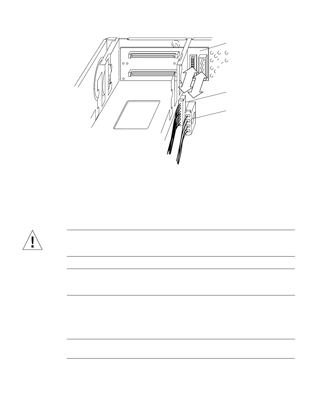
FIGURE 8-39 SCSI Backplane, SCSI Data, and DC Power Connectors
Installing the DC Power Harness (SunCD 2Plus
Drive-Type Chassis)
Caution – Use proper ESD grounding techniques when handling components. Wear
an antistatic wrist strap and use an ESD-protected mat. Store ESD-sensitive
components in antistatic bags before placing it on any surface.
Note – Tape or tie-wrap markers on internal cables help in properly routing the
cables through the metal cable guides. The part of each cable with a marker is to be
visible between the metal cable guides on the chassis bottom.
1. Place the DC power harness and SCSI data cable as follows (
FIGURE 8-39):
a. Route the end of the DC power harness with connectors P1 and P3 through the
sheetmetal opening in the drive bracket.
Note – Be sure the tie wrap markers are in the proper position beneath the metal
cable guides.
DC power
connector (P3)
SCSI data
connector (P1)
SCSI backplane
clip

 Loading...


