SunFounder ESP32 Starter Kit
COMPONENT INTRODUCTION PURCHASE LINK
ESP32 WROOM 32E
ESP32 Camera Extension -
Jumper Wires
Ultrasonic Module
Available Pins
• Available Pins
Here is a list of available pins on the ESP32 board for this project.
For Input IO13, IO14, IO27, IO26, IO25, IO33, IO32, I35, I34, I39, I36, IO4, IO18,
IO19, IO21, IO22, IO23
For Output IO13, IO12, IO14, IO27, IO26, IO25, IO33, IO32, IO15, IO2, IO0, IO4, IO5,
IO18, IO19, IO21, IO22, IO23
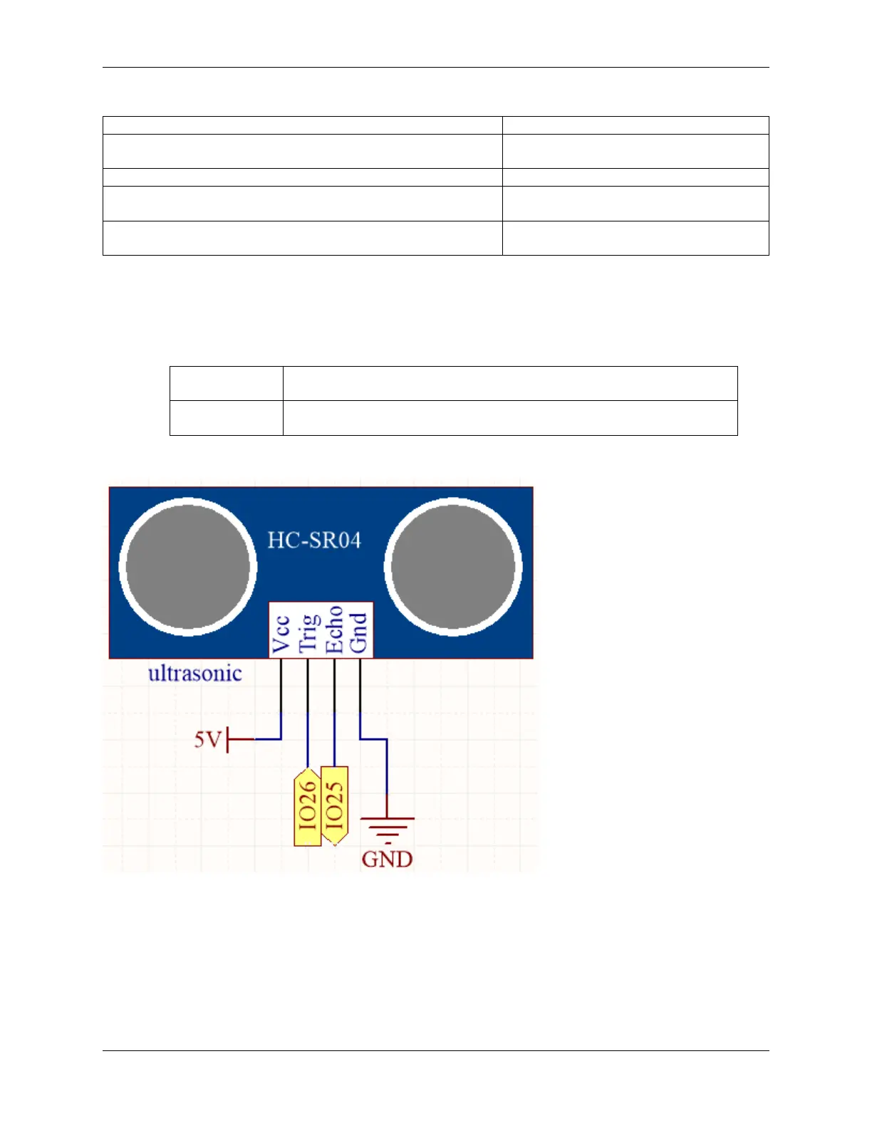
Schematic
The ESP32 sends a set of square wave signals to the Trig pin of the ultrasonic sensor every 10 seconds. This prompts
the ultrasonic sensor to emit a 40kHz ultrasound signal outward. If there is an obstacle in front, the ultrasound waves
will be reflected back.
By recording the time it takes from sending to receiving the signal, dividing it by 2, and multiplying it by the speed of
light, you can determine the distance to the obstacle.
Wiring
1.28. 5.12 Measuring Distance 97