SunFounder ESP32 Starter Kit
COMPONENT INTRODUCTION PURCHASE LINK
ESP32 WROOM 32E
ESP32 Camera Extension -
Breadboard
Jumper Wires
Resistor
LED
Available Pins
Here is a list of available pins on the ESP32 board for this project.
Available Pins IO13, IO12, IO14, IO27, IO26, IO25, IO33, IO32, IO15, IO2, IO0, IO4, IO5, IO18, IO19,
IO21, IO22, IO23
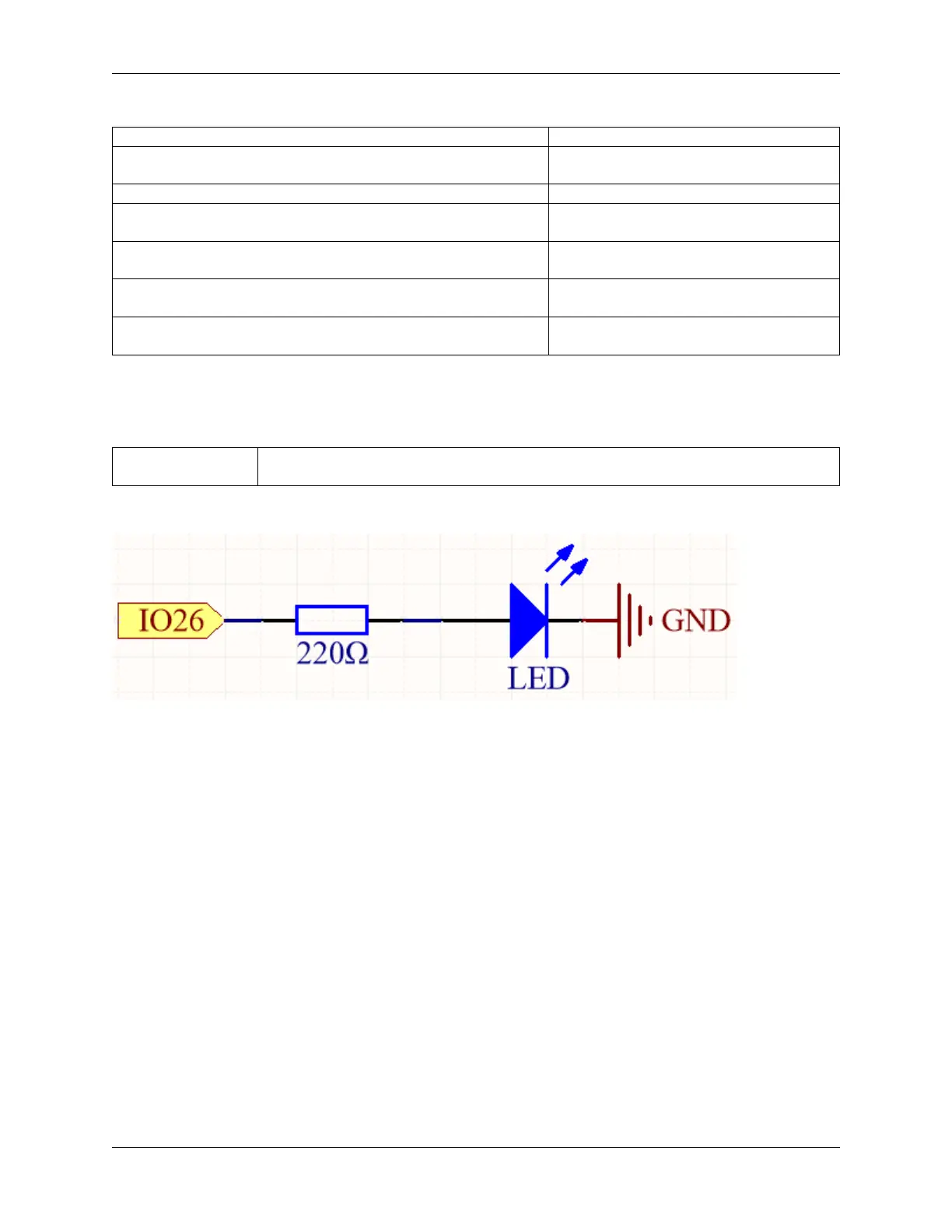
Schematic
This circuit works on a simple principle, and the current direction is shown in the figure. The LED will light up after
the 220ohm current limiting resistor when pin26 outputs high level. The LED will turn off when pin26 outputs low
level.
Wiring
1.5. 2.1 Hello, LED! 19