SunFounder ESP32 Starter Kit
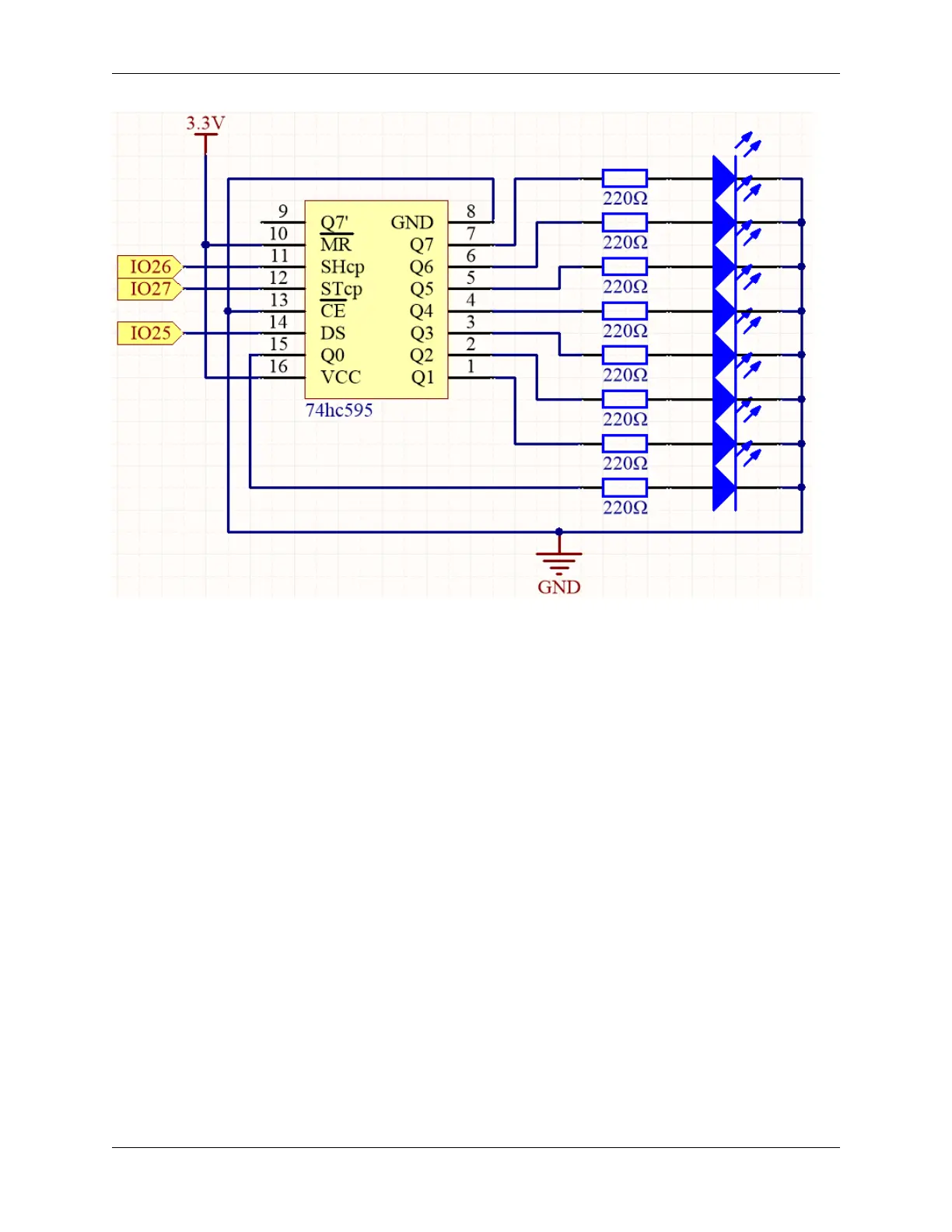
• When MR (pin10) is high level and CE (pin13) is low level, data is input in the rising edge of SHcp and goes to
the memory register through the rising edge of SHcp.
• If the two clocks are connected together, the shift register is always one pulse earlier than the memory register.
• There is a serial shift input pin (DS), a serial output pin (Q7’) and an asynchronous reset button (low level) in
the memory register.
• The memory register outputs a Bus with a parallel 8-bit and in three states.
• When OE is enabled (low level), the data in memory register is output to the bus(Q0 ~ Q7).
Wiring
32 Chapter 1. For Arduino User