SunFounder ESP32 Starter Kit
COMPONENT INTRODUCTION PURCHASE LINK
ESP32 WROOM 32E
ESP32 Camera Extension -
Breadboard
Jumper Wires
Resistor
7-segment Display
74HC595
Available Pins
Here is a list of available pins on the ESP32 board for this project.
Available Pins IO13, IO12, IO14, IO27, IO26, IO25, IO33, IO32, IO15, IO2, IO0, IO4, IO5, IO18, IO19,
IO21, IO22, IO23
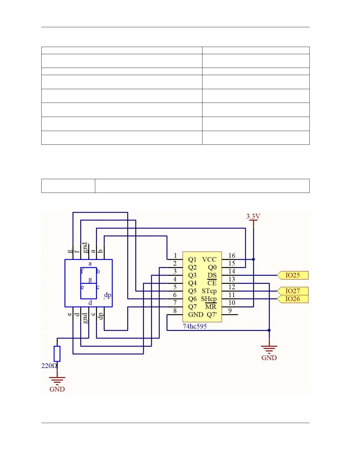
Schematic
Here the wiring principle is basically the same as 2.4 Microchip - 74HC595, the only difference is that Q0-Q7 are
connected to the a ~ g pins of the 7 Segment Display.
1.9. 2.5 7 Segment Display 35