SunFounder ESP32 Starter Kit
COMPONENT INTRODUCTION PURCHASE LINK
ESP32 WROOM 32E
ESP32 Camera Extension -
Breadboard
Jumper Wires
Resistor
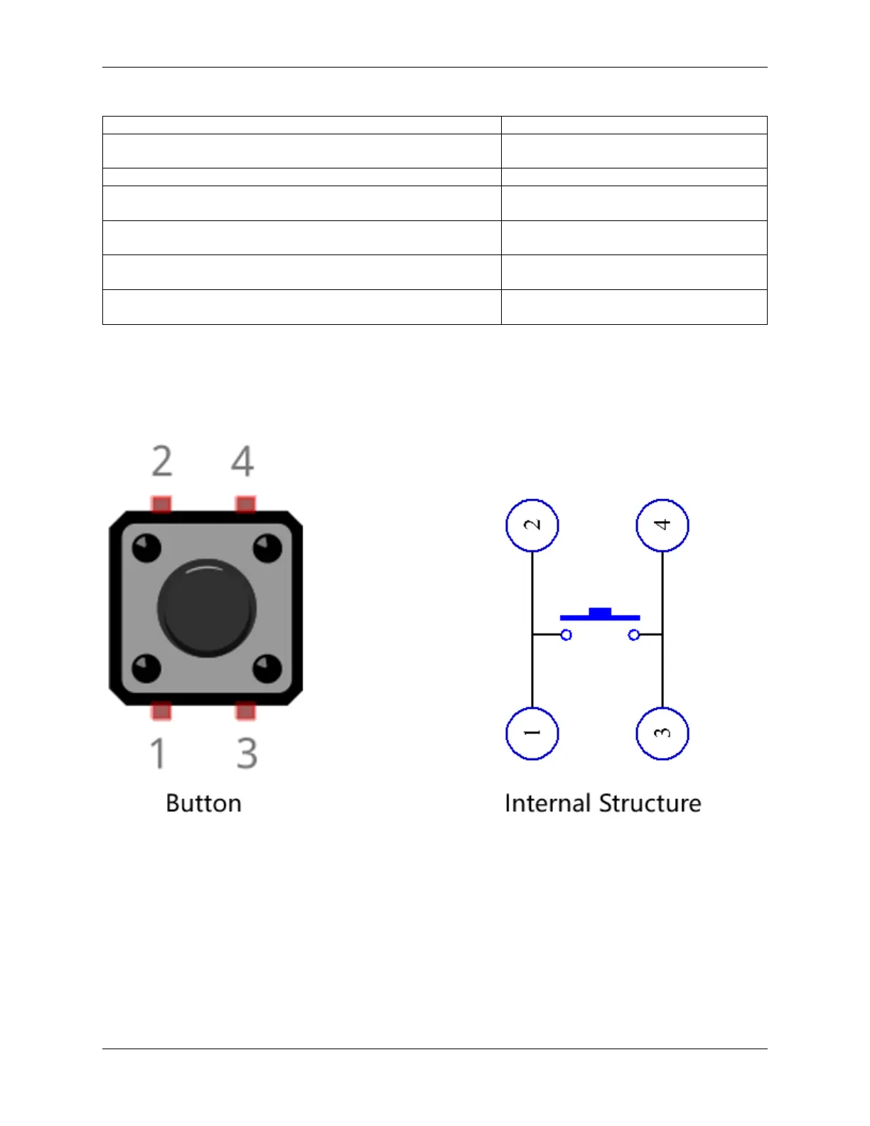
Button
4.17.2 Build the Circuit
The button is a 4-pin device, since the pin 1 is connected to pin 2, and pin 3 to pin 4, when the button is pressed, the 4
pins are connected, thus closing the circuit.
Build the circuit according to the following diagram.
• Connect one of the pins on the left side of the button to pin14, which is connected to a pull-down resistor and a
0.1uF (104) capacitor (to eliminate jitter and output a stable level when the button is working).
• Connect the other end of the resistor and capacitor to GND, and one of the pins on the right side of the button to
5V.
580 Chapter 4. Play with Scratch