SunFounder ESP32 Starter Kit
COMPONENT INTRODUCTION PURCHASE LINK
ESP32 WROOM 32E
ESP32 Camera Extension -
Breadboard
Jumper Wires
Resistor
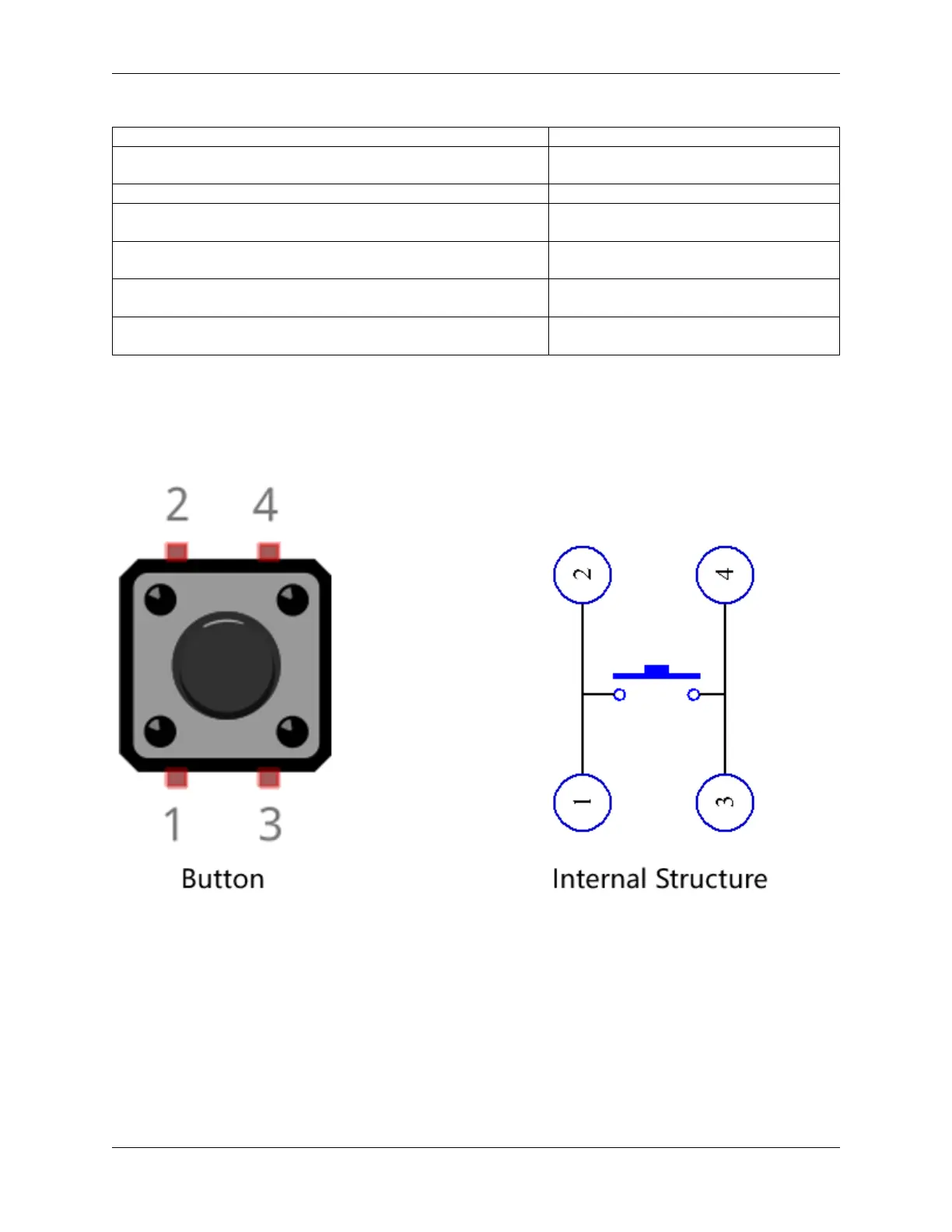
Button
4.20.2 Build the Circuit
The button is a 4-pin device, since the pin 1 is connected to pin 2, and pin 3 to pin 4, when the button is pressed, the 4
pins are connected, thus closing the circuit.
Build the circuit according to the following diagram.
• Connect one of the pins on the left side of the button to pin14, which is connected to a pull-down resistor and a
0.1uF (104) capacitor (to eliminate jitter and output a stable level when the button is working).
• Connect the other end of the resistor and capacitor to GND, and one of the pins on the right side of the button to
5V.
4.20. 2.17 GAME - Fishing 611