SunFounder ESP32 Starter Kit
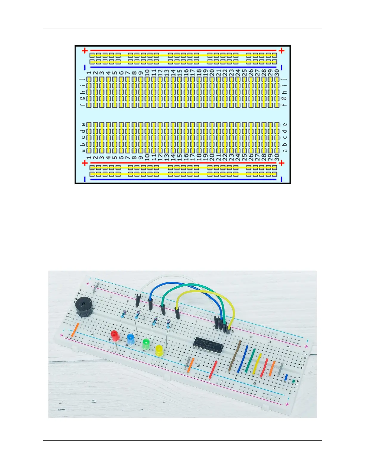
As shown in the diagram, each set of five holes in the middle section, columns A-E or F-J, is electrically connected.
This means, for example, that hole A1 is electrically connected to holes B1, C1, D1 and E1.
It is not connected to hole A2 because that hole is in a different row with a separate set of metal clips. It is also not
connected to holes F1, G1, H1, I1 or J1 because they are located in the other “half” of the breadboard - the clips are
not connected across the middle gap.
Unlike the middle section, which is grouped by five holes, the buses on sides are electrically connected separately.
For example, the column marked blue (-) is electrically connected as a whole, and the column marked red (+) is also
electrically connected.
Which electronic parts are compatible with breadboards?
Many electronic components have long metal legs called leads. Almost all components with leads will work with a
692 Chapter 5. Learn about the Components in Your Kit