SunFounder ESP32 Starter Kit
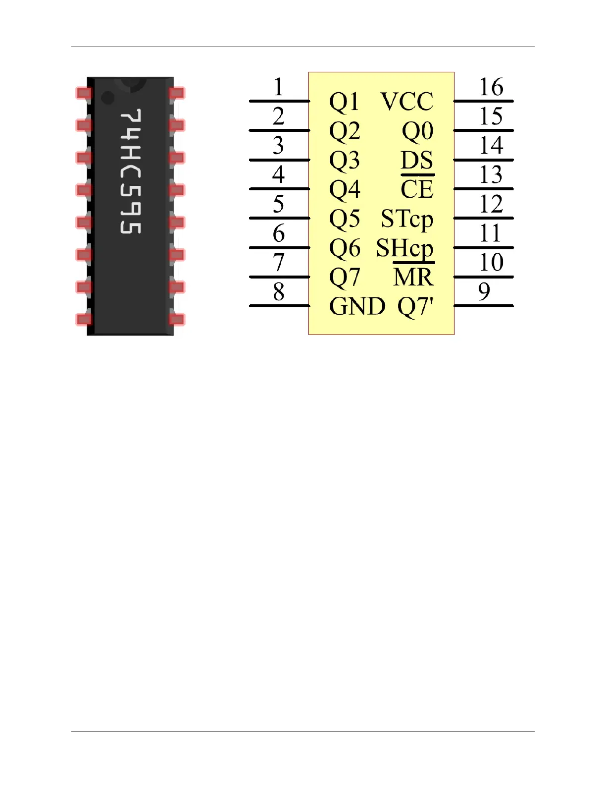
• Q0-Q7: 8-bit parallel data output pins, able to control 8 LEDs or 8 pins of 7-segment display directly.
• Q7’: Series output pin, connected to DS of another 74HC595 to connect multiple 74HC595s in series
• MR: Reset pin, active at low level;
• SHcp: Time sequence input of shift register. On the rising edge, the data in shift register moves successively
one bit, i.e. data in Q1 moves to Q2, and so forth. While on the falling edge, the data in shift register remain
unchanged.
• STcp: Time sequence input of storage register. On the rising edge, data in the shift register moves into memory
register.
• CE: Output enable pin, active at low level.
• DS: Serial data input pin
• VCC: Positive supply voltage.
• GND: Ground.
Functional Diagram
702 Chapter 5. Learn about the Components in Your Kit