8
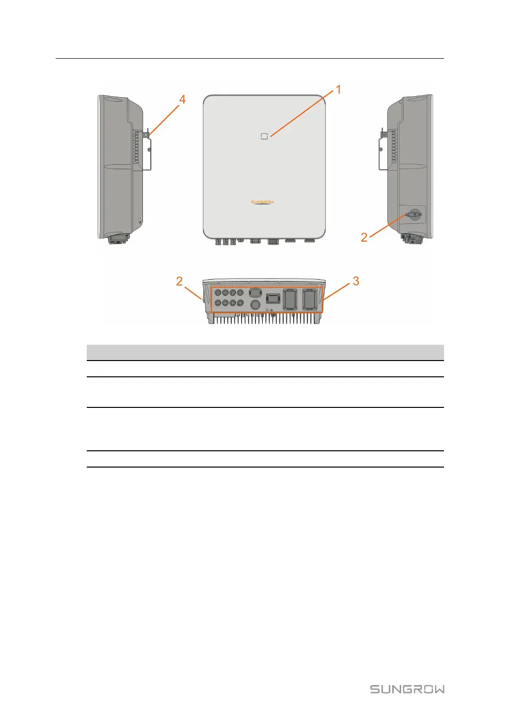
figure 2-1 Inverter Appearance
No. Name
Description
1
LED indicator panel Indicates the current working state of the inverter.
2
DC switch(Optional)
Used to disconnect PV - only when there is no PV
production.
3
Electrical connection
area
Includes DC terminals, AC terminals, battery terminals,
communication terminals and additional grounding
terminal.
4
Hanger Used to hang the inverter on the wall-mounting bracket.
Dimensions
The following figure shows the dimensions of the inverter.
2 Product Description User Manual