45
6.3 Electrical Connection Overview
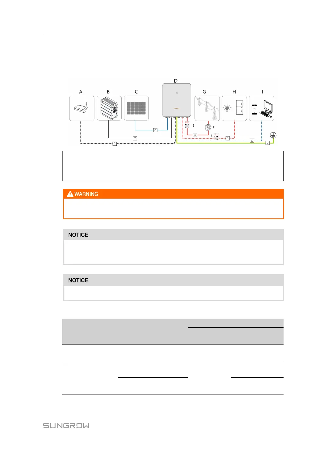
System Wiring Diagram
The electrical connection should be realized as follows:
(A) Router (B) Battery (C) PV string
(D) Inverter (E) AC circuit breaker (F) Smart Energy Meter
(G) Grid (H) Backup loads (I) Monitoring device
Install an AC circuit breaker on the backup side. Otherwise, an electrical short cir-
cuit may occur, causing damage to the inverter.
Ensure that AC output cables are firmly connected. Failing to do so may cause in-
verter malfunction or damage to its AC connectors.
Make sure not to switch the phase order (L1-L3) which may cause malfunction.
table 6-3 Cable requirements
N-
o.
Cable
Type
Specification
Outer
diameter
Cross section
1 Ethernet cable
CAT 5E outdoor shielded
network cable
5.3 ~ 7 mm 8 * 0.2 mm²
2 Power Cable
Complying with 1,000V
and 35A standard
5.5 ~ 8 mm
4 mm²
Complying with 1,000V
and 40A standard
6 mm²
User Manual 6 Electrical Connection