16
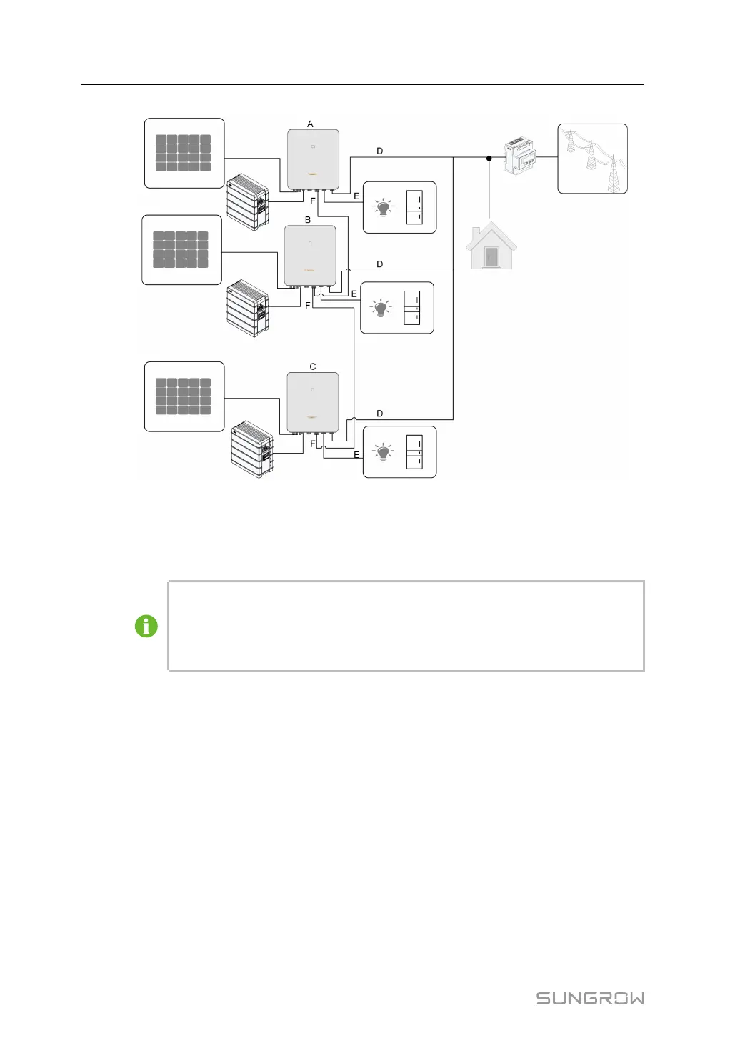
figure 2-4 Parallel PV ESS
(A) Master (B) Slave 1 (C) Slave 2
(D) GRID (E) BACK-UP (F) RS485
Only the hybrid GRID terminals can be connected in parallel, the BACK-UP termi-
nals and the battery terminals cannot be connected together. Each hybrid must
have its own BACK-UP loads. The Backup loads of each inverter should not ex-
ceed its nominal power.
Refer to "6.7.3 RS485 Connection" for the cable connection.
In an on-grid parallel system, the master inverter collects information from Smart Energy
Meter and slave inverter and performs the energy management including:
• Feed-in power control.
• Battery charge / discharge
• Maximum power limitation
The following settings are required for the inverter parallel function.
• Feed-in power control. The feed-in power control function refers to "8.5.1 Feed-in Limita-
tion". The PV installation power of the master inverter is the total installation power of the
system, the slave inverters do not need to set the feed-in power.
2 Product Description User Manual