User Manual 11 Appendix IV: Power Response
95
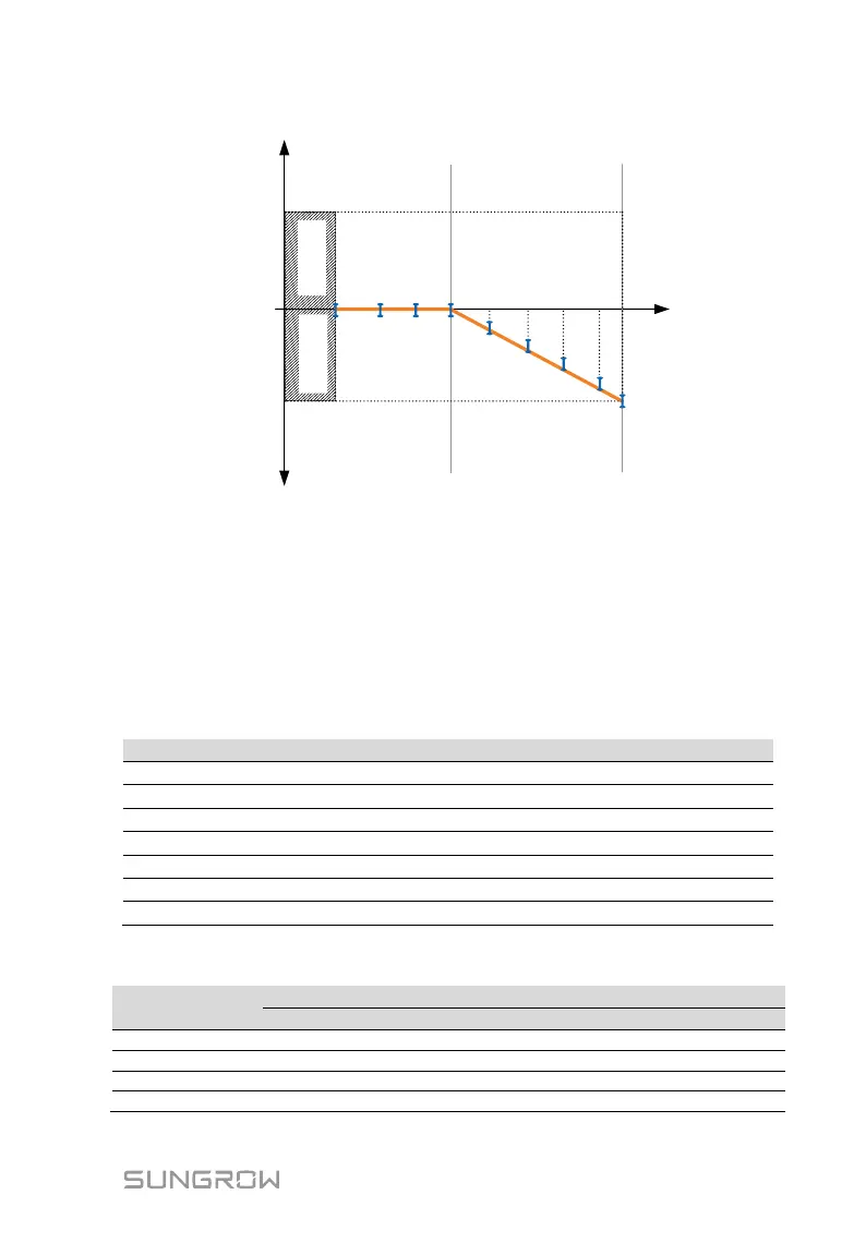
COS Ф
1.0
0.9
0.9
Power (P/Prated, %)
50%
100%
Inductive
Capacitive
0.2 0.3 0.4 0.5 0.6 0.7 0.8 0.9
Fig. 11-1 Reactive Power Regulation Curve in Q(P) Mode
11.1.3 “Q(U)” Mode
Define the response curve with four grid voltages, leading Q/Sn of the lower
limit point and lagging Q/Sn of the upper limit point. The reactive power output
of the inverter will vary in response to the grid voltage.
The Q(U) parameters can only be set via the iSolarCloud App or the
iSolarCloud server.
Tab. 11-2 “Q(U)” Mode Parameter Explanations
Grid voltage limit (in %) of point P1 in the Q(U) mode curve
Grid voltage limit (in %) of point P2 in the Q(U) mode curve
Grid voltage limit (in %) of point P3 in the Q(U) mode curve
Grid voltage limit (in %) of point P4 in the Q(U) mode curve
Leading Q/Sn value of point P1 in the Q(U) mode curve
Lagging Q/Sn value of point P4 in the Q(U) mode curve
Hysteresis voltage width (in %)
* V2 Ref. + Hysteresis < V3 Ref. Hysteresis
Tab. 11-3 “Q(U)” Mode Parameter Values