EasyManua.ls Logo

Sungrow SH3K6 - Result Verification Procedures

Sungrow SH3K6
118 pages
Print Icon
To Next Page IconTo Next Page
To Previous Page IconTo Previous Page
Loading...
User Manual 7 Commissioning
63
7.4 Result Verification
7.4.1 Energy Meter Installation and Connection
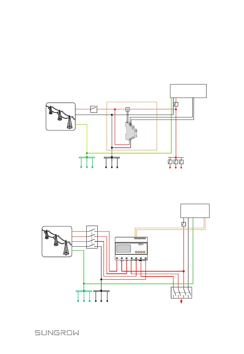
For the single-phase Energy Meter, with the signal from the 1-phase sensor, the
inverter determines the energy exchange with the utility grid on one phase. The
CT clamp of 1-phase sensor can be placed before or after the main switch.
L
A
B
L
N
N
PE
PE bar
Neutral bar
Main Switch
SUNGROW
Meter
Utility Grid
Inverter
Solar
switch
Home appliance
1
-
phase sensor
Fig. 7-3 Correct Installation and Connection of the Single-phase Energy Meter
The following figure shows the correct installation and connection of the
three-phase Energy Meter.
SUNGROW
Meter
L3
N
PE
PE bar Neutral bar
Home appliance
Main Switch
AC circuit breaker
Utility Grid
L1
L2
A
Load side
Grid side
Inverter
B
SET
21 22 17 18 19 20
L1 L1 L2 L2 L3 L3 N
Fig. 7-4 Correct Installation and Connection of the Three-phase Energy Meter

Table of Contents

Other manuals for Sungrow SH3K6

Related product manuals