7 Commissioning User Manual
64
Before the verification, disconnect the DC switch between the inverter and the
battery module.
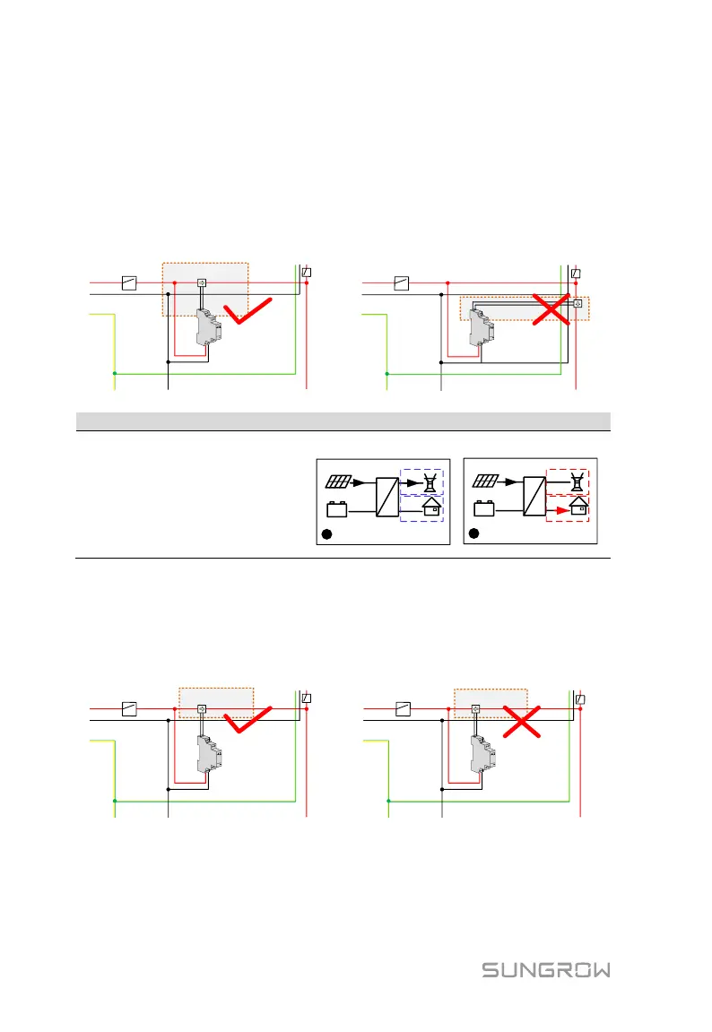
For Incorrect Installation Position
Make sure that the 1-phase sensor of the Sungrow Energy Meter should be
placed to the phase line (L) from the main switch. If otherwise, the energy flow
indicated on the LCD will be wrong.
L
L
N
N
PE
PE bar
Neutral bar
Main switch
SUNGROW
Meter
1
-
phase sensor
Inverter
Home appliance
L
L
N
N
PE
PE bar
Neutral bar
SUNGROW
Meter
1-phase sensor
Inverter
Home appliance
Main switch
Turn off all the household loads.
All the PV power generation
should be exported to the grid,
as shown in the “Correct” figure.
4000
=
~
0
4000
0
12:37
(W)
+
-
Running
C
4000
=
~
0
0
4000
12:37
(W)
+
-
Running
C
Correct
Wrong
For Reverse Sensor Connection
Make sure that the arrow on the 1-phase sensor must point away from the grid
towards the load. If otherwise, the energy flow indicated on the LCD will be
wrong.
L
L
N
N
PE
PE bar
Neutral bar
Main switch
SUNGROW
Meter
1
-
phase sensor
Inverter
Home appliance
L
L
N
N
PE
PE bar
Neutral bar
Main switch
SUNGROW
Meter
1
-
phase sensor
Inverter
Home appliance
Fig. 7-5 Correct CT Installation for Single-phase Energy Meter