6 Electrical Connection User Manual
50
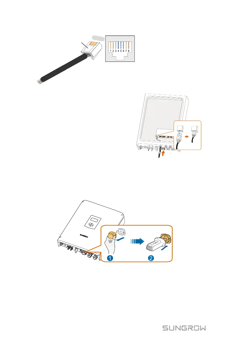
Corresponding Relationship Between
Cables and Pins:
Pin 1: White-orange; Pin 2: Orange;
Pin 3: White-green; Pin 4: Blue;
Pin 5: White-blue; Pin 6: Green;
Pin 7: White-brown; Pin 8: Brown.
RJ45 Port
RJ45 plug
1
----
8
4. Install the RJ45 plug to the
Ethernet port.
5. Fasten the swivel nut and connect
the other end to the socket of the
switch or the router.
6.5.2 Wi-Fi Connection
1. Unscrew the waterproof lid from the Wi-Fi terminal.
2. Install the Wi-Fi module. Slightly shake it by hand to determine whether it
is installed firmly, as shown below.
3. Refer to the quick guide for the Wi-Fi module to configure the Wi-Fi.