User Manual 6 Electrical Connection
51
6.6 Battery Connection
This section mainly describes the cable connections on the inverter side. Refer
to the instructions supplied by the battery manufacturer for the connections on
the battery side.
Only use properly insulated tools to prevent accidental electric shock
or short circuits. If insulated tools are not available, use electrical tape
to cover the entire exposed metal surfaces of the available tools except
their tips.
6.6.1 Connecting the Power Cable
A fuse with the specification of 150 V/125 A (type: Bussmann BS88 125LET) is
integrated to the BAT- terminal.
A two-pole DC circuit breaker with over-current protection (voltage
rating not less than 100 V and current rating not less than 100 A)
should be installed between the inverter and the battery module.
Cable Requirements
Cross-section: 16 mm
2
...25 mm
2
, OT25-6, cable diameter: 13 mm...16 mm.
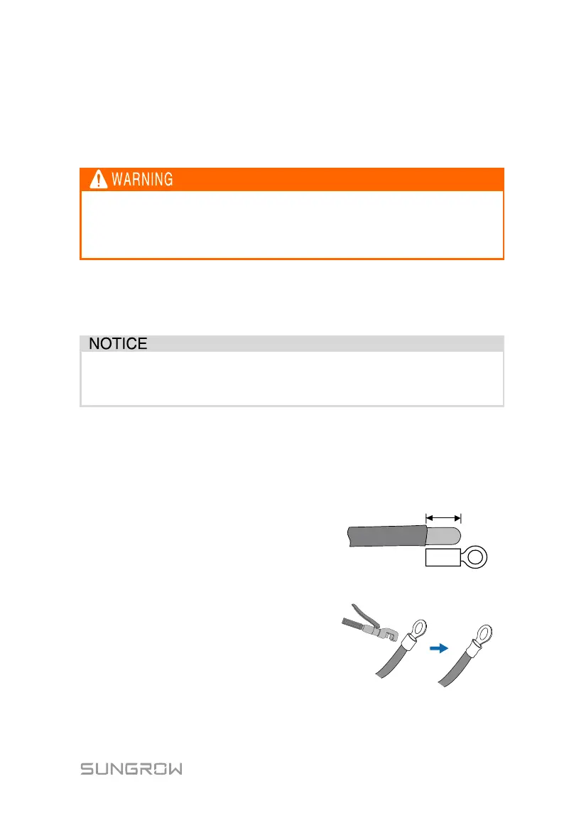
Procedure:
1. Remove the battery cable
jacket.
2. Crimp the OT terminal and
install the heat shrinkable
casing.