3 Function Description User Manual
18
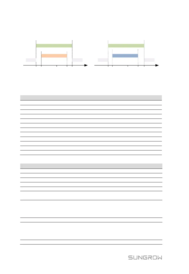
voltage level goes back to normal levels after the disturbance.
Grid voltage, V
V1 V2 VmaxVmin Vn
Normal operation
Start-up
Standby
Standby
V3 V4Vn
Reconnection
Standby Standby
Grid voltage, V
Condition 1: initial start-up Condition 2: reconnection after protection
VmaxVmin
Normal operation
Fig. 3-3 Inverter Action related to Grid Voltage (“DE” for example)
Tab. 3-1 Operational Voltage Parameter Description
Lower voltage limit for initial start-up
Upper voltage limit for initial start-up
Lower voltage limit for reconnection
Upper voltage limit for reconnection
Connection or recovery gradient
Under-voltage protection value
Over-voltage protection value
Under-voltage protection time
Over-voltage protection time
Tab. 3-2 Default Values of Operational Voltage Parameter
25 % Pn/min or
10 % Pn/min
(1)
Not applicable or 10 %
Pn/min
(2)
184.0 for stage I
103.5 for stage II,
195.5 for
stage I
34.5 for
stage II
3.0 for stage I,
0.3 for stage II
1.5 for stage
I,
0.2 for stage
II