Getting Started
11
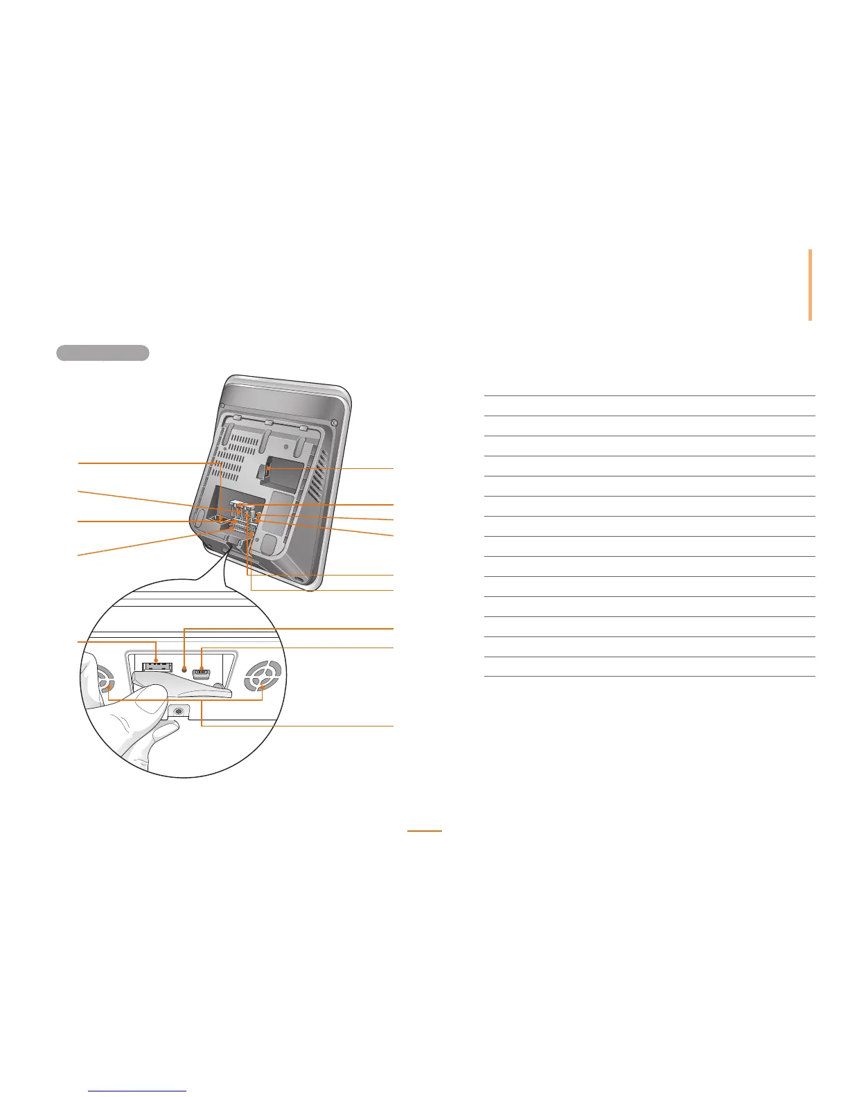
Rear and Bottom
1
2
3
4
10
11
12
13
5
6
8
9
7
14
1
USB Wireless LAN Port Used for the wireless LAN module.
2
Termination Switch Enables RS485 termination.
3
PWR Connectors Connects to the 2-pin power cable.
4
RS232 Connectors Connects to the 3-pin RS232 cable.
5
RS485 Connectors Connects to the 4-pin RS485 cable.
6
Wiegand Connectors Connects to the 5-pin Wiegand cable.
7
Reset Button Resets the device.
8
Mini USB Port Connects with a PC.
9
Speaker Audio output from the device
10
USB type A Port Connects to a USB memory device.
11
Input Terminal Connects to the 8-pin input cable.
12
Analogue Video Connects to the 7-pin analogue video phone cable.
13
Output Relay Terminal Connects to two 3-pin relay cables.
14
Ethernet Port Connects an Ethernet cable.