7A-12 Heater and Ventilation:
4) Connect battery positive (+) terminal to terminal “b”
and battery positive (–) terminal to terminal “a”.
Check if position of air flow control actuator changes
DEF position to VENT position.
If malfunction is found, replace air flow control
actuator with new one.
Temperature Control Actuator Removal and
Installation
S5JB0A7106015
Removal
1) Disconnect negative (–) cable at battery.
2) Remove steering column hole cover from instrument
panel.
3) Disconnect temperature control actuator connector
(2).
4) Remove screws (3) and then, remove temperature
control actuator (1) from HVAC unit.
Installation
Reverse removal procedure.
Temperature Control Actuator Inspection
S5JB0A7106016
1) Remove temperature control actuator (1). Refer to
“Temperature Control Actuator Removal and
Installation: ”.
2) Check resistance between “d” and “e” terminals.
Temperature control actuator resistance
Max cold position: Approx. 480 Ω
Max hot position: Approx. 3.9 kΩ
3) Connect battery positive (+) terminal to terminal “b”
and battery negative (–) terminal to terminal “a”.
Check if position of actuator lever changes COLD
position to HOT position.
4) Connect battery positive (+) terminal to terminal “a”
and battery positive (–) terminal to terminal “b”.
Check if position of actuator lever changes HOT
position to COLD position.
If malfunction is found, replace temperature control
actuator with new one.
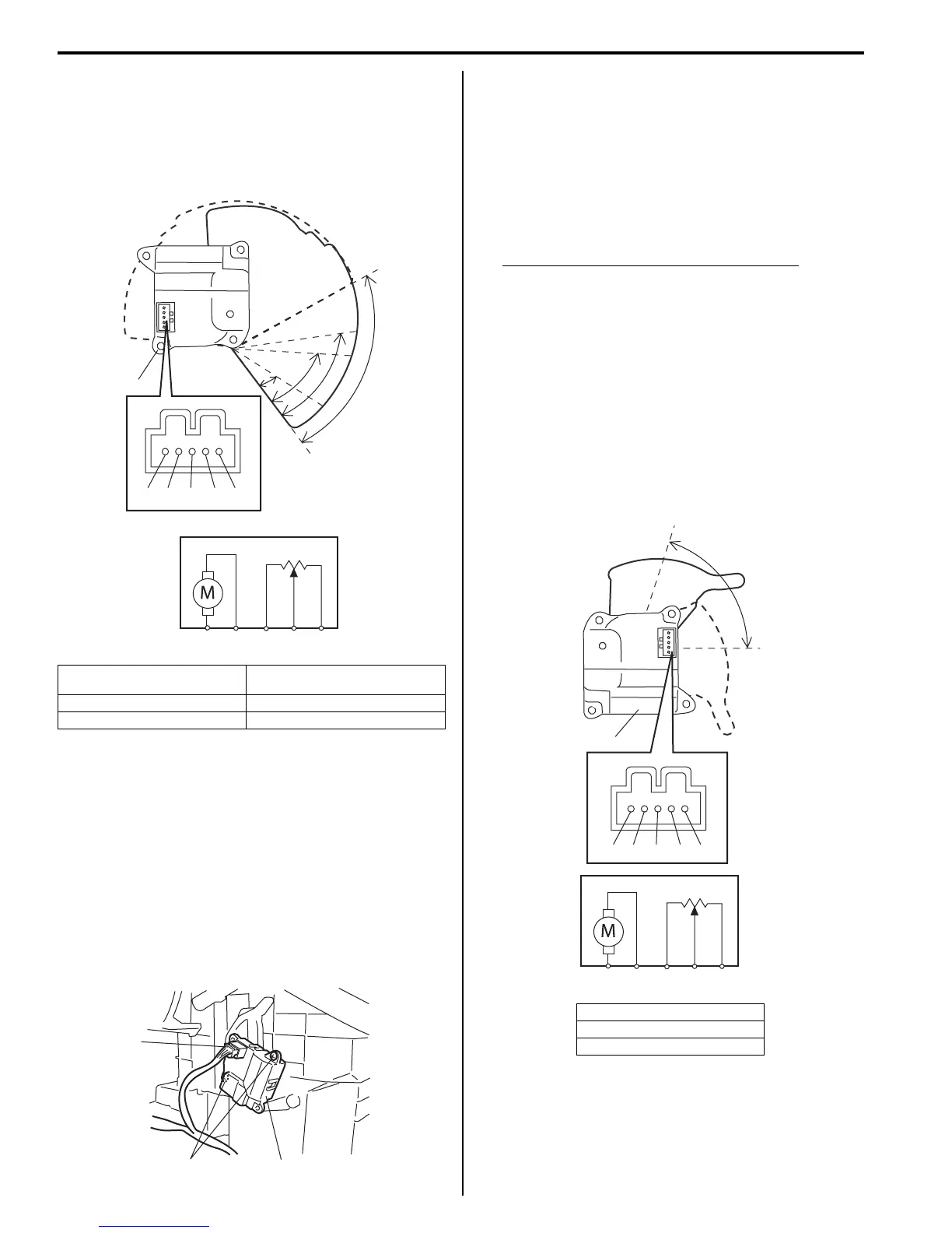
A: VENT position D: DEF / FOOT position (Approx.
50°)
B: BI-LEVEL position (Approx. 22°) E: DEF position
C: FOOT position (Approx. 40°) F: Approx. 82°
“a” “b” “c” “d” “e”
E
D
C
B
F
A
1
“a” “b” “c” “d” “e”
I5JB0A710015-03
2
1
3
I5JB0A710016-01
A: Max cold position
B: Max hot position
C: Approx. 72°
“a” “b” “c” “d” “e”
A
C
B
1
“a” “b” “c” “d” “e”
I5JB0A710017-03

 Loading...