Heater and Ventilation: 7A-13
Air Intake Control Actuator Removal and
Installation
S5JB0A7106017
Removal
1) Disconnect negative (–) cable at battery.
2) Remove glove box.
3) Disconnect air intake control actuator connector (2).
4) Remove screws and then, remove air intake control
actuator (1) from HVAC unit.
Installation
Reverse removal procedure.
Air Intake Control Actuator Inspection
S5JB0A7106018
1) Remove air intake control actuator (1). Refer to “Air
Intake Control Actuator Removal and Installation: ”.
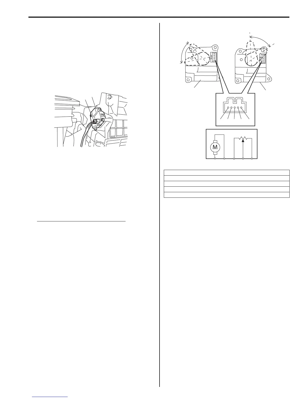
2) Check resistance between “d” and “e” terminals of
actuator.
Air intake control actuator resistance
LH steering vehicle
REC position: Approx. 4.5 kΩ
FRE position: Approx. 1.2 kΩ
RH steering vehicle
REC position: Approx. 1.2 kΩ
FRE position: Approx. 4.5 kΩ
3) Connect battery positive (+) terminal to terminal “a”
and battery negative (–) terminal to terminal “b”.
Check if position of actuator lever is REC position.
4) Connect battery positive (+) terminal to terminal “b”
and battery negative (–) terminal to terminal “a”.
Check if position of actuator lever is FRESH position.
Actuator Linkage Inspection
S5JB0A7106019
• Check if each actuator linkage operates smoothly.
• Check actuator rod for bend.
• Check each actuator linkage for breakage.
• Make sure if there is not any obstruction in operating
range of actuator linkage.
If any malfunction is found, repair or replace faulty
part(s).
1
2
I5JB0A710018-01
[A]: LH steering vehicle
[B]: RH steering vehicle
C: REC position
D: FRESH position
E: Approx. 60°
“a”
“b” “c” “d” “e”
“a” “b” “c” “d” “e”
1
C
E
D
C
E
[A] [B]
D
1
I5JB0A710019-03

 Loading...