7B-55 Air Conditioning System:
DTC B1562: Outside Air Temperature Sensor and/or Its Circuit Malfunction
S5JB0A7204049
DTC Detecting Condition and Trouble Area
DTC Troubleshooting
DTC B1563: A/C Refrigerant Pressure Sensor and/or Its Circuit Malfunction
S5JB0A7204050
DTC Detecting Condition and Trouble Area
DTC Troubleshooting
HVAC Control Module and Its Circuits Inspection
S5JB0A7204052
CAUTION
!
HVAC control module can not be checked by itself.
It is strictly prohibited to connect voltmeter to HVAC control module with couplers disconnected from
it.
HVAC control module and its circuits can be checked at HVAC control module wiring couplers by measuring voltage.
Voltage Check
1) Remove HVAC control module. Refer to “HVAC Control Module Removal and Installation: in Section 7A”.
2) Connect HVAC control module and body control module couplers to HVAC control module and body control
module.
3) Check each terminal voltage with couplers connected by referring to “HVAC Control Module Voltage Table: ”.
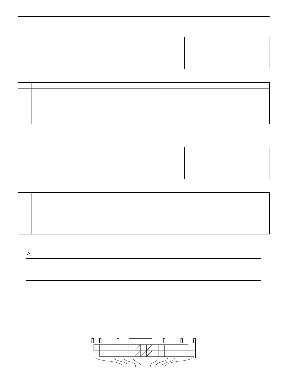
Terminal arrangement of HVAC control module (viewed from harness side)
DTC detecting condition Trouble area
HVAC control module receives error code from BCM continuously. • Outside air temperature sensor
circuit
• Outside air temperature sensor
• HVAC control module
Step Action Yes No
1 DTC check
1) Connect scan tool to DLC with ignition switch turned
OFF.
2) Check BCM for DTC.
Are there DTC B1141, B1142 or B1143?
Go to applicable DTC
diag. flow.
Substitute a known-
good HVAC control
module and recheck.
DTC detecting condition Trouble area
HVAC control module receives error code from BCM continuously. • A/C refrigerant pressure sensor
circuit
• A/C refrigerant pressure sensor
• HVAC control module
Step Action Yes No
1 DTC check
1) Connect scan tool to DLC with ignition switch turned
OFF.
2) Check ECM for DTC.
Are there DTC P0532 or P0533?
Go to applicable DTC
diag. flow.
Substitute a known-
good HVAC control
module and recheck.
16 15 14 13 12 11 10 8 6 5 4 3 2 1
32 31 30 29 28 27 23 22 21 20 19 18 17
I5JB0A720030-02

 Loading...