Body Electrical Control System: 10B-29
Inspection of BCM and its Circuits
S5JB0AA204017
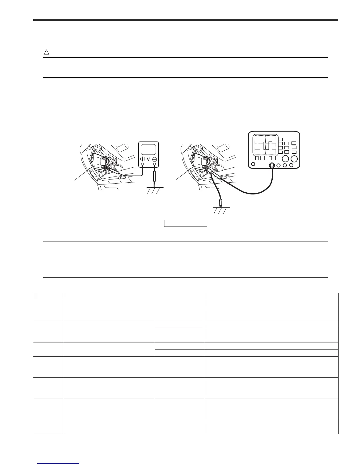
BCM and its circuits can be checked at BCM wiring couplers by measuring voltage and resistance.
CAUTION
!
BCM cannot be checked by itself. It is strictly prohibited to connect voltmeter or ohmmeter to BCM
with couplers disconnected from it.
Voltage Check
1) Disconnect negative cable (–) at battery.
2) Remove steering column hole cover from instrument panel.
3) Check voltage at each terminal number of couplers connected.
For connector and terminal number, refer to “Connector Layout Diagram of BCM: ”.
NOTE
• As each terminal voltage is affected by the battery voltage, confirm that it is 11 V or more when
ignition switch is ON.
• Voltage with asterisk (*) can not be measured by voltmeter because it is pulse signal.
Check it with oscilloscope if necessary.
BCM connector “G30”
11
I5JB0AA20012-01
1. BCM
Terminal Circuit Normal voltage Condition
G30-1 Power source (IG)
10 – 14 V Ignition switch is at ON position
0 V
Ignition switch is at any position other than ON
position
G30-2 Power source (ACC)
10 – 14 V Ignition switch is at ACC or ON position
0 V
Ignition switch is at any position other than ACC or
ON position
G30-3 Key reminder switch
10 – 14 V Ignition key is inserted to ignition key cylinder
0 V Ignition key is pulled out from ignition key cylinder
G30-4
Serial communication line for
HVAC control module
*0 – 1 V
↑↓
10 – 14 V
Refer to “Reference waveform No. 1: ”
G30-5
Serial communication line for
information display and HVAC
control module
*0 – 1V
↑↓
10 – 14 V
Refer to “Reference waveform No. 2: ”
G30-6 Rear wiper switch
*0 – 1 V
↑↓
10 – 14 V
Refer to “Reference waveform No. 3: ”
0 V
Ignition switch is at ON position and rear wiper
switch is at ON position

 Loading...