Cruise Control System: 10A-6
Inspection of Cruise Control System Circuit
S5JB0AA104012
Cruise control system is controlled by ECM. Each switch and circuit can be checked by taking measurement of
terminal voltage and terminal to terminal resistance of ECM. When measuring these values, be sure to read
precautions for measurement described under “Inspection of ECM and Its Circuits: in Section 1A”.
Voltage Check
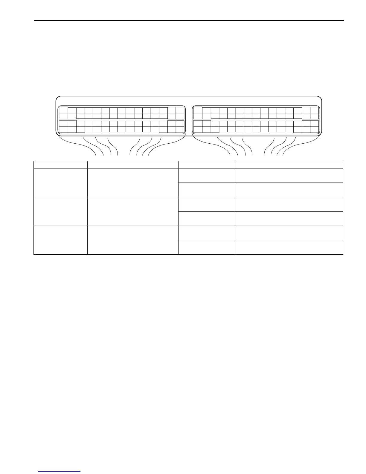
Check voltage between the following terminals with ECM connector connected.
Terminal arrangement of ECM connector viewed from harness side
E23 C37
34
1819
5671011
1720
47 46495051
2122
52
1625
9
24
14
29
5557 54 53
59
60 58
2
262728
15
30
56 48
32 31343536374042 39 38
44
45 43 41 33
11213
23
834
1819
5671011
1720
47 46495051
2122
52
1625
9
24
14
29
5557 54 53
59
60 58
2
262728
15
30
56 48
32 31343536374042 39 38
44
45 43 41 33
11213
23
8
I5JB0AA10004-01
Terminals Circuit Normal Voltage Condition
E23-7 – ground CPP switch circuit
10 – 14 V
Ignition switch is at ON position and
clutch pedal is not depressed.
0 V
Ignition switch is at ON position and
clutch pedal is depressed.
E23-8 – ground Stop (Brake) lamp switch circuit
10 – 14 V
Ignition switch is at ON position and
brake pedal is not depressed.
0 V
Ignition switch is at ON position and
brake pedal is depressed.
E23-20 – ground Stop (Brake) lamp switch circuit
0 V
Ignition switch is at ON position and
brake pedal is not depressed.
10 – 14 V
Ignition switch is at ON position and
brake pedal is depressed.

 Loading...