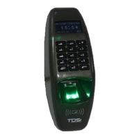
Installation
DIGIgarde PLUS User Guide
Copyright
©
2012 TDSi Last Change
Page 14 13 May, 2016
2.3.2
2.3.22.3.2
2.3.2 Wiring guide
Wiring guideWiring guide
Wiring guide
DIGIgarde PLUS can be connected to other devices (access control units, lock,
door sensor, alarm, host PC etc) through the colour-coded and labelled connection
cables. In addition to the connections described in Table 5, there is also a pre-
configured RJ-45 connector.
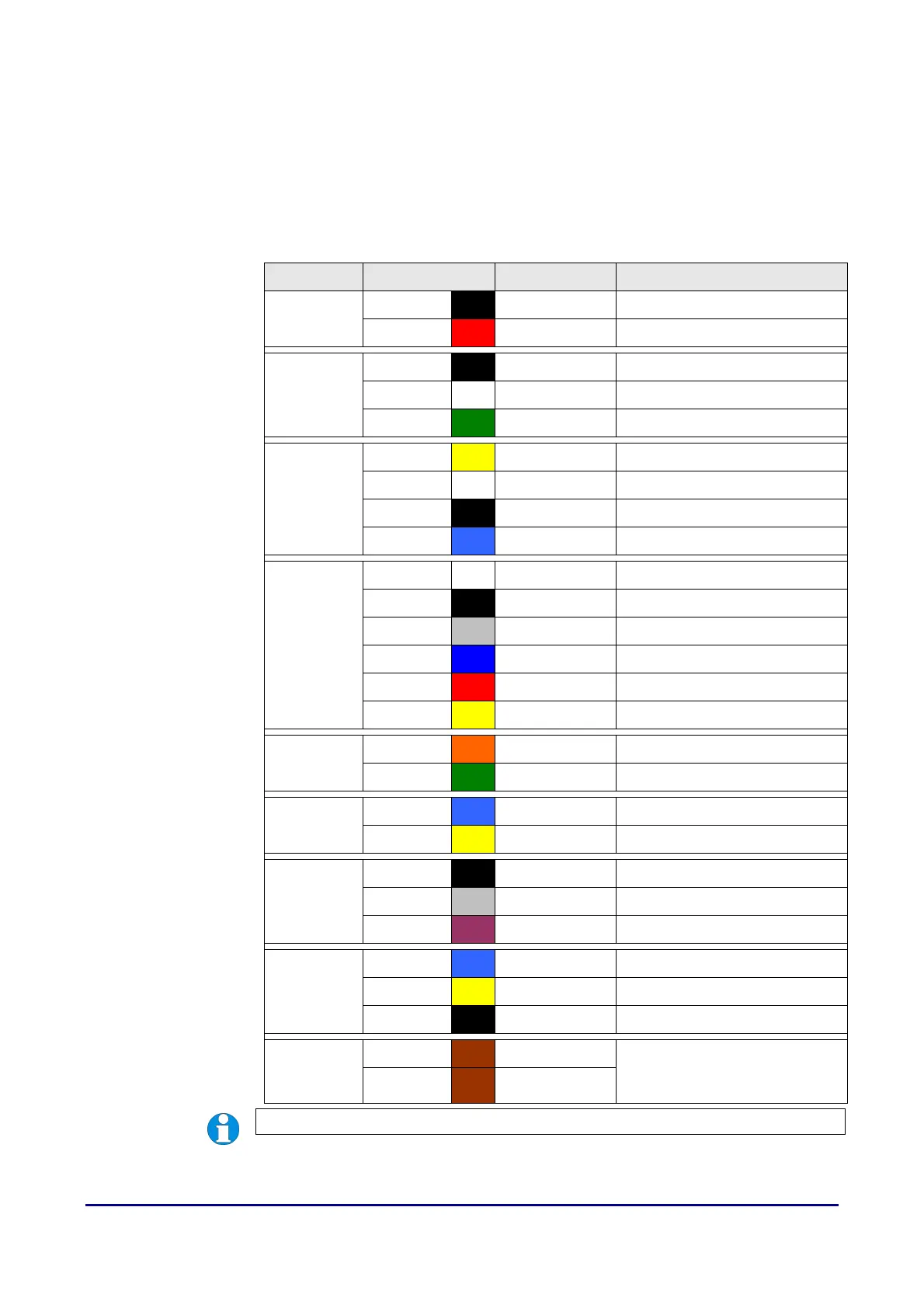
Table 5 Cable Assignments
Label Wire Colour Signal Description
Power
Black 0V Power GND
Red +12V Power Input
WG IN
Black GND GND
White WD0-IN Wiegand Input, Data 0
Green WD1-IN Wiegand Input, Data 1
WG OUT
Yellow WD0-OUT Wiegand Output, Data 0
White WD1-OUT Wiegand Output, Data 1
Black GND Wiegand GND
Blue LED LED
Lock
White SENSOR Door Sensor power
Black GND Door Sensor ground
Grey BUTTON Egress button
Blue NO1 Normally Open
Red COM1 Common
Yellow NC1 Normally Closed
Alarm
Orange ALARM NO2 Alarm (Normally Open)
Green ALARM COM2 Alarm (Common)
RS485-2
Blue RS-485A-2 RX+, RS-485-2 level
Yellow RS-485B-2 RX-, RS-485-2 level
RS232
Black RS-232 0V RS-232 0V
Grey RS-232 RX Receive Data, RS-232C level
Purple RS-232 TX Transmit Data, RS-232C level
RS485-1
Blue RS-485A-1 RX+, RS-485-1 level
Yellow RS-485B-1 RX-, RS-485-1 level
Black GND RS-485 GND
RS485RES
Brown RS-485RES Link wires to provide
termination resistor
(see page 19).
Brown RS-485RES
NOTE. RS232 and RS485 connections are not available on current build.