Installation
DIGIgarde PLUS User Guide
Copyright
©
2012 TDSi Last Change
Page 16 13 May, 2016
2.3.5
2.3.52.3.5
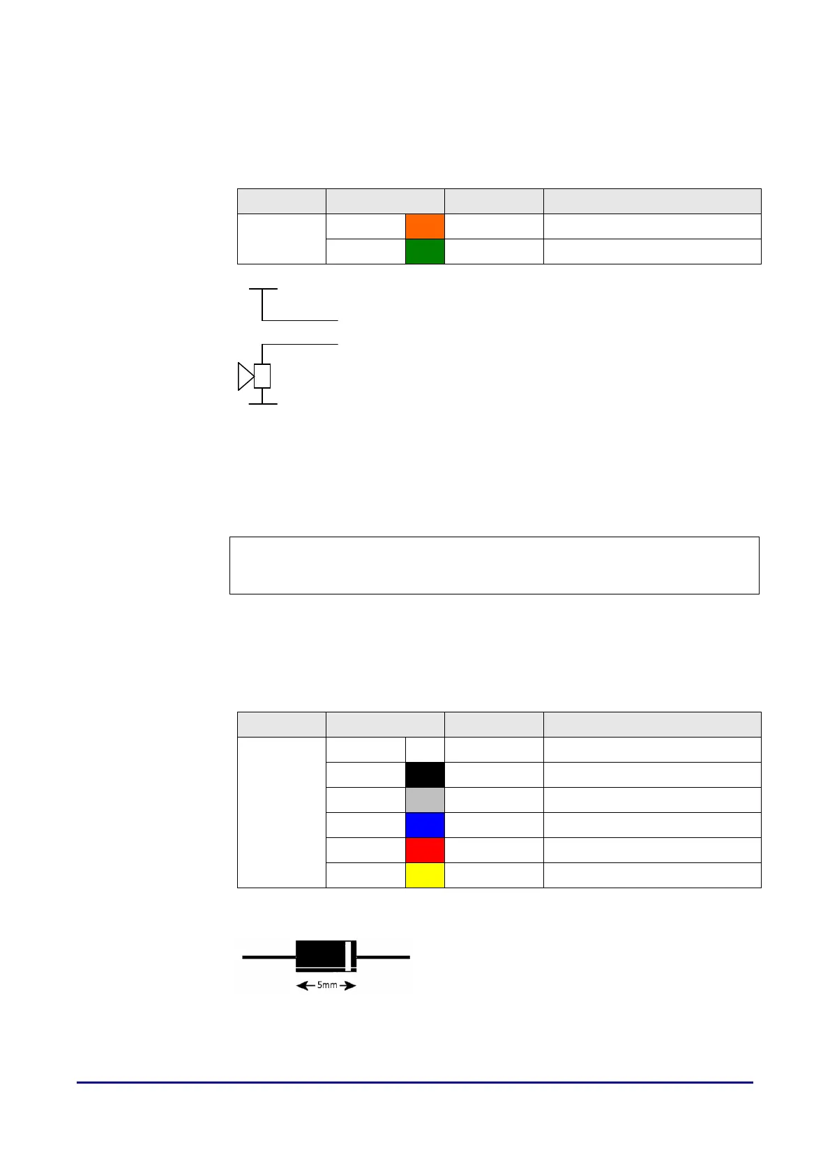
2.3.5 Alarm connection
Alarm connectionAlarm connection
Alarm connection
To use an external alarm (see page 16) for indicating repeated failed verification,
an unexpected door open/closed state, duress access or for help indication,
connect the alarm power lines to the marked orange and green wires.
Label Wire Colour Signal Description
Alarm
Orange ALARM - Alarm -
Green ALARM + Alarm +
Figure 8 Alarm connection
2.3.6
2.3.62.3.6
2.3.6 Lock and Sensor connection
Lock and Sensor connectionLock and Sensor connection
Lock and Sensor connection
CAUTION! A suppressor MUST be fitted at each lock (see below). Suitable
suppressors (1N4003 diodes) are provided with each MICROgarde controller
and can be purchased separately from TDSi.
For each lock, allow 50% more than stated power rating. For example, if the lock
has a rating of 500mA, use a 750mA minimum supply. If the lock has a higher
current rating than the lock relay (2A?), use a secondary relay.
Never run the power supply and sensor or communication lines in the same cable.
Label Wire Colour Signal Description
Lock
White SENSOR Door Sensor power
Black GND Door Sensor ground
Grey BUTTON Egress button
Blue NO Normally Open
Red COM Common
Yellow NC Normally Closed
Fitting a suppressor
Fitting a suppressorFitting a suppressor
Fitting a suppressor
Fit a suppressor across the lock supply as close to
the lock as possible with the white band end
connected to the positive side of the supply.
V+
0V
Alarm +
Alarm -