FLEXability LINE: Service & Maintenance Manual - rev. 1.0
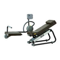
6.7. ENCODER DEVICE
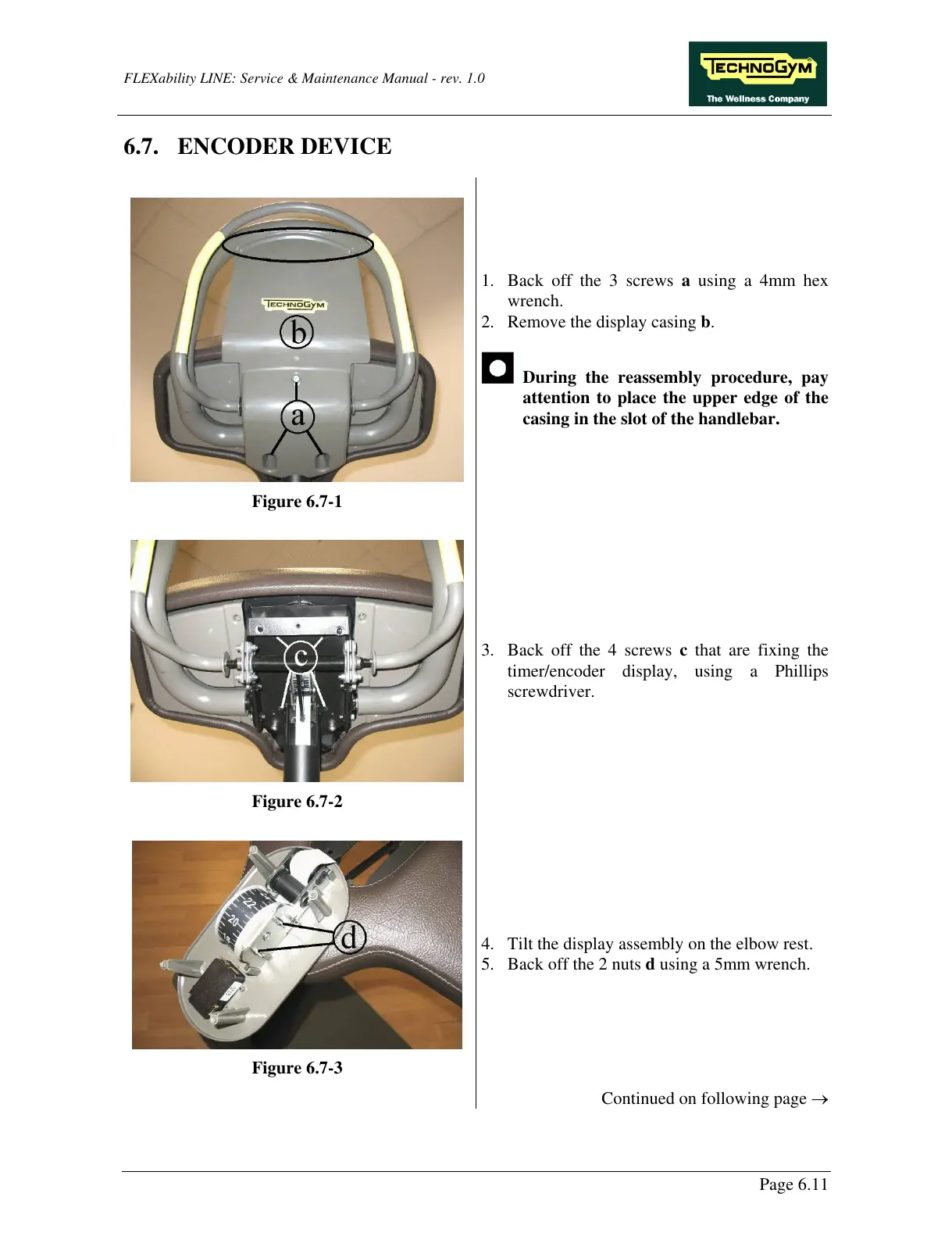
Figure 6.7-1
1. Back off the 3 screws a using a 4mm hex
wrench.
2. Remove the display casing b.
During the reassembly procedure, pay
attention to place the upper edge of the
casing in the slot of the handlebar.
Figure 6.7-2
3. Back off the 4 screws c that are fixing the
timer/encoder display, using a Phillips
screwdriver.
Figure 6.7-3
4. Tilt the display assembly on the elbow rest.
5. Back off the 2 nuts d using a 5mm wrench.
Continued on following page →
Page 6.11