FLEXability LINE: Service & Maintenance Manual - rev. 1.0
Page 6.16
6.9. BRAKE LEVER
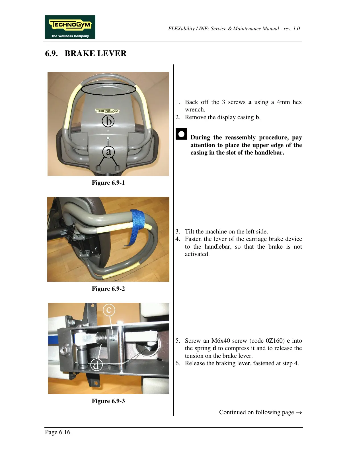
Figure 6.9-1
1. Back off the 3 screws a using a 4mm hex
wrench.
2. Remove the display casing b.
During the reassembly procedure, pay
attention to place the upper edge of the
casing in the slot of the handlebar.
Figure 6.9-2
3. Tilt the machine on the left side.
4. Fasten the lever of the carriage brake device
to the handlebar, so that the brake is not
activated.
Figure 6.9-3
5. Screw an M6x40 screw (code 0Z160) c into
the spring d to compress it and to release the
tension on the brake lever.
6. Release the braking lever, fastened at step 4.
Continued on following page →