FLEXability LINE: Service & Maintenance Manual - rev. 1.0
Page 7.14
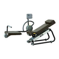
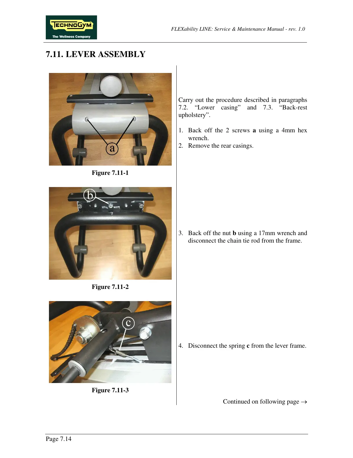
7.11. LEVER ASSEMBLY
Figure 7.11-1
Carry out the procedure described in paragraphs
7.2. “Lower casing” and 7.3. “Back-rest
upholstery”.
1. Back off the 2 screws a using a 4mm hex
wrench.
2. Remove the rear casings.
Figure 7.11-2
3. Back off the nut b using a 17mm wrench and
disconnect the chain tie rod from the frame.
Figure 7.11-3
4. Disconnect the spring c from the lever frame.
Continued on following page →