FLEXability LINE: Service & Maintenance Manual - rev. 1.0
7.9. ENCODER ASSEMBLY
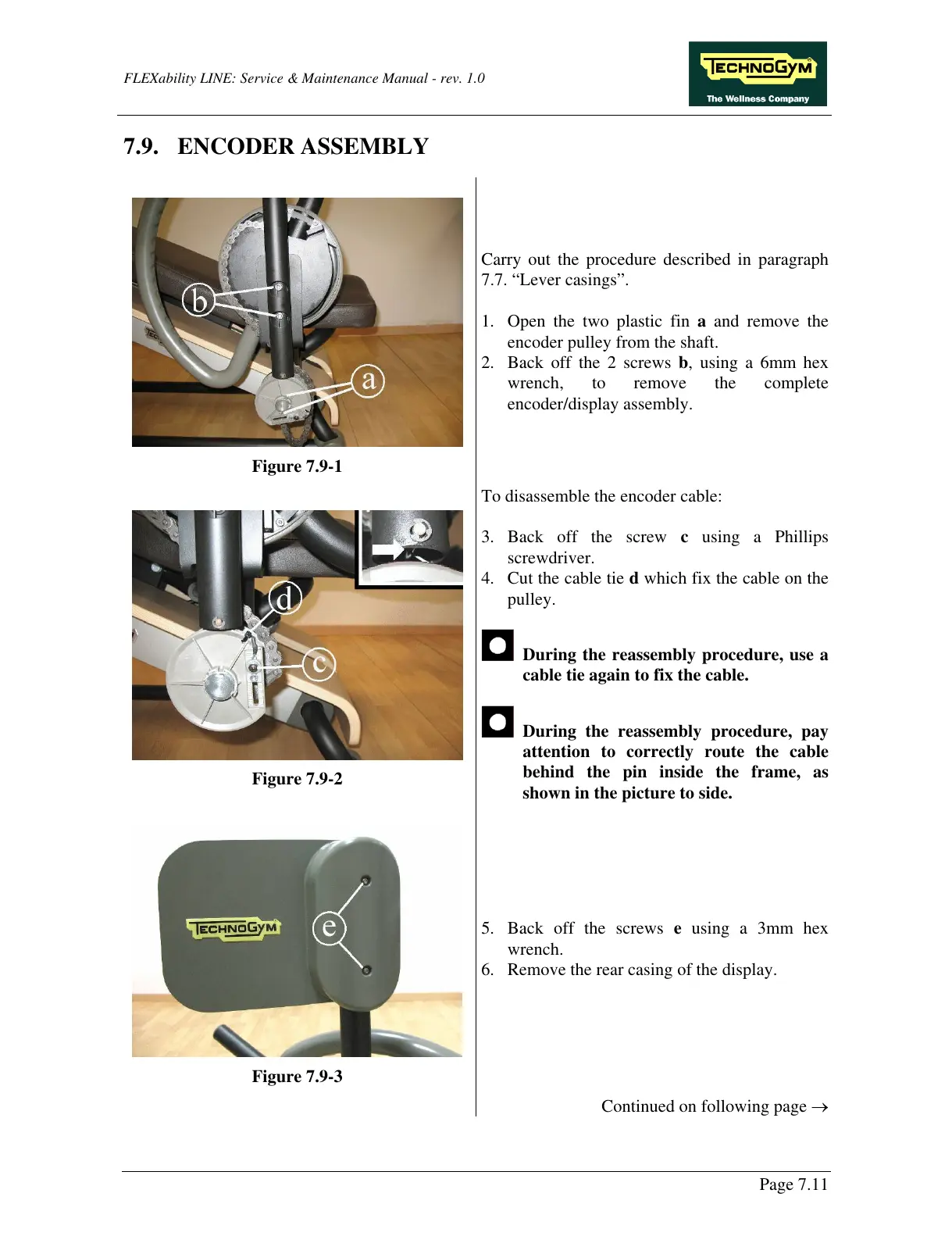
Figure 7.9-1
Carry out the procedure described in paragraph
7.7. “Lever casings”.
1. Open the two plastic fin a and remove the
encoder pulley from the shaft.
2. Back off the 2 screws b, using a 6mm hex
wrench, to remove the complete
encoder/display assembly.
Figure 7.9-2
To disassemble the encoder cable:
3. Back off the screw c using a Phillips
screwdriver.
4. Cut the cable tie d which fix the cable on the
pulley.
During the reassembly procedure, use a
cable tie again to fix the cable.
During the reassembly procedure, pay
attention to correctly route the cable
behind the pin inside the frame, as
shown in the picture to side.
Figure 7.9-3
5. Back off the screws e using a 3mm hex
wrench.
6. Remove the rear casing of the display.
Continued on following page →
Page 7.11