FLEXability LINE: Service & Maintenance Manual - rev. 1.0
Page 7.16
7.12. BACK-REST CARRIAGE
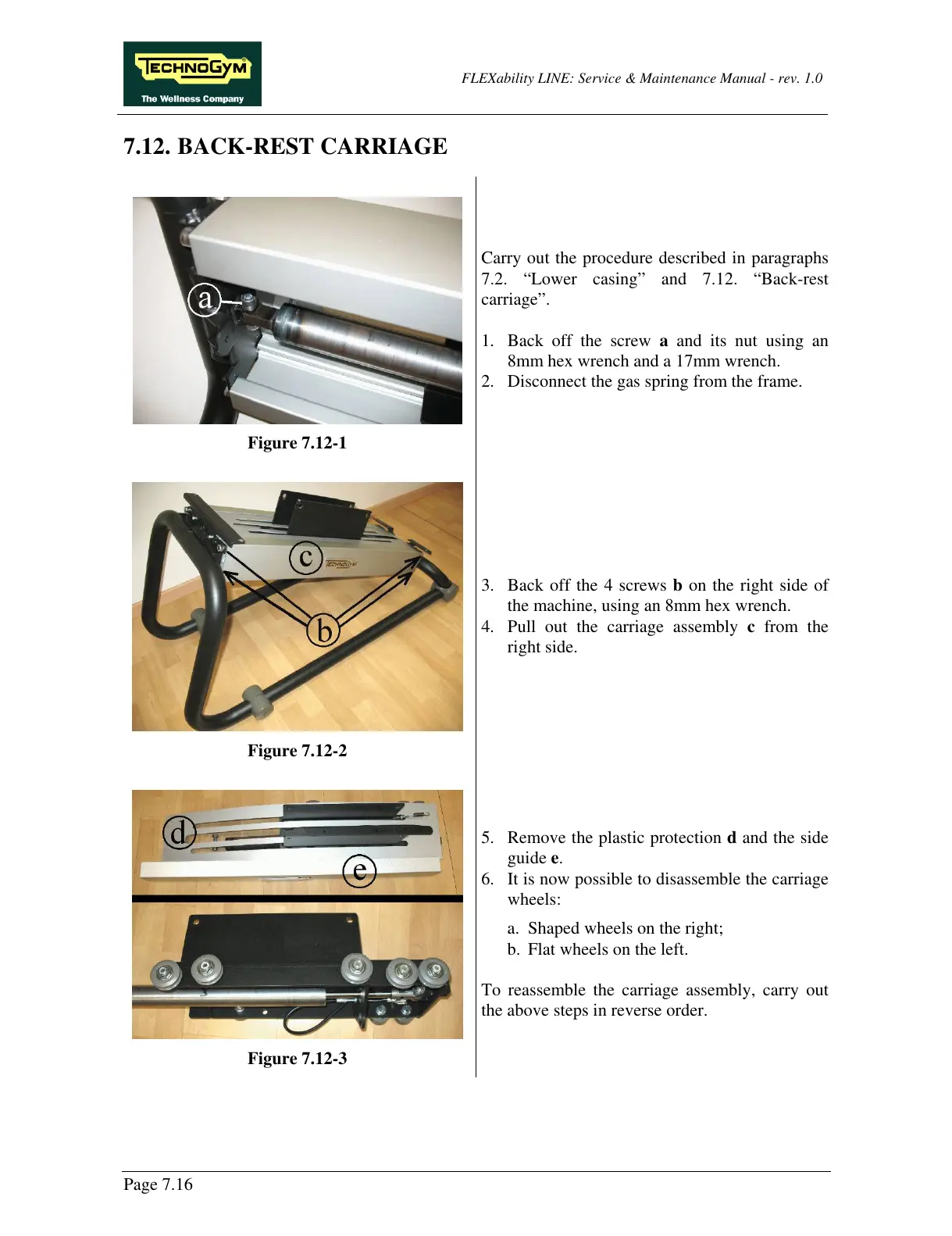
Figure 7.12-1
Carry out the procedure described in paragraphs
7.2. “Lower casing” and 7.12. “Back-rest
carriage”.
1. Back off the screw a and its nut using an
8mm hex wrench and a 17mm wrench.
2. Disconnect the gas spring from the frame.
Figure 7.12-2
3. Back off the 4 screws b on the right side of
the machine, using an 8mm hex wrench.
4. Pull out the carriage assembly c from the
right side.
Figure 7.12-3
5. Remove the plastic protection d and the side
guide e.
6. It is now possible to disassemble the carriage
wheels:
a. Shaped wheels on the right;
b. Flat wheels on the left.
To reassemble the carriage assembly, carry out
the above steps in reverse order.