FLEXability LINE: Service & Maintenance Manual - rev. 1.0
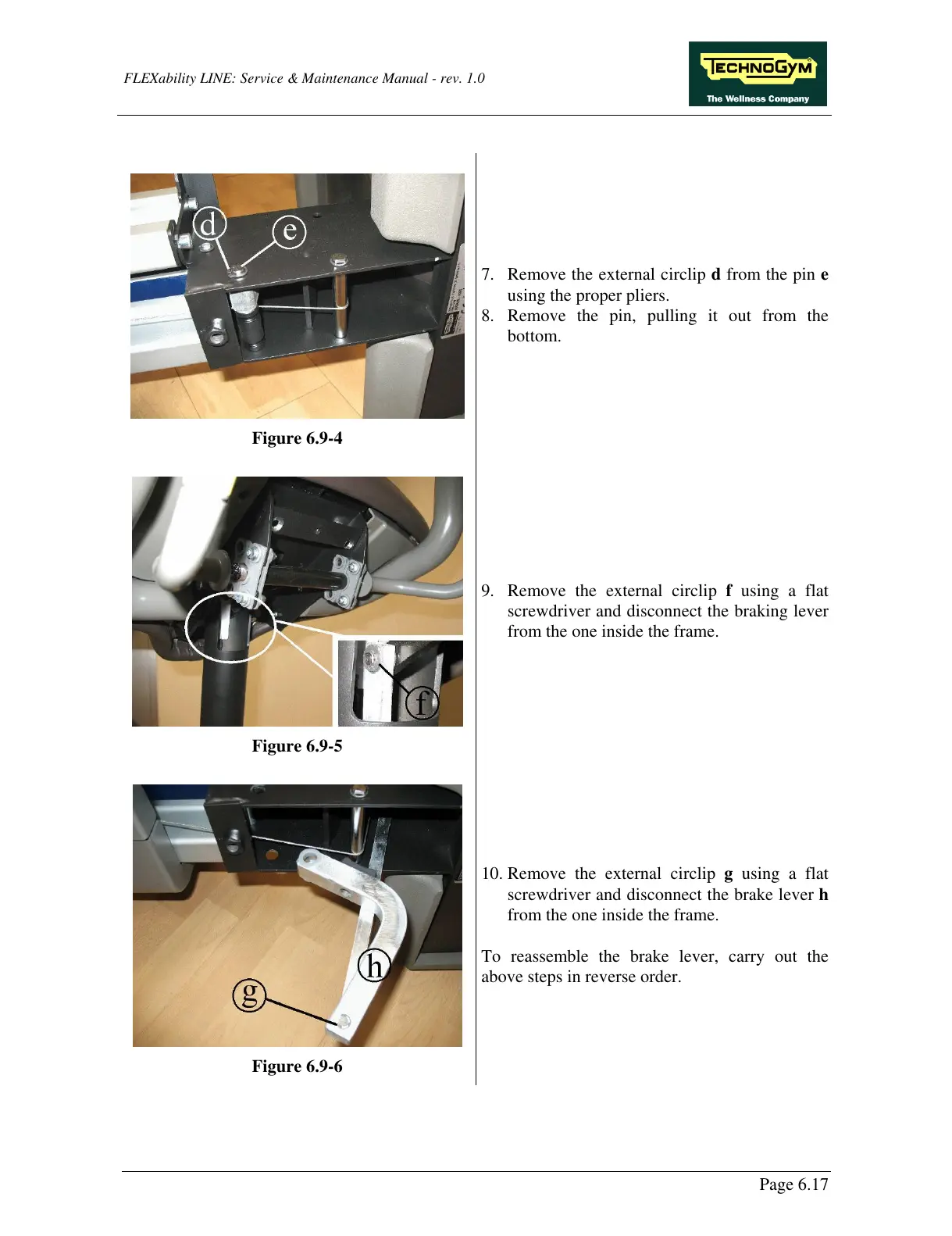
Figure 6.9-4
7. Remove the external circlip d from the pin e
using the proper pliers.
8. Remove the pin, pulling it out from the
bottom.
Figure 6.9-5
9. Remove the external circlip f using a flat
screwdriver and disconnect the braking lever
from the one inside the frame.
Figure 6.9-6
10. Remove the external circlip g using a flat
screwdriver and disconnect the brake lever h
from the one inside the frame.
To reassemble the brake lever, carry out the
above steps in reverse order.
Page 6.17