FORMA: Service & Maintenance manual - rev. 3.0
Page 3.6
3.2.3. T
HE SIGNALS INVOLVED
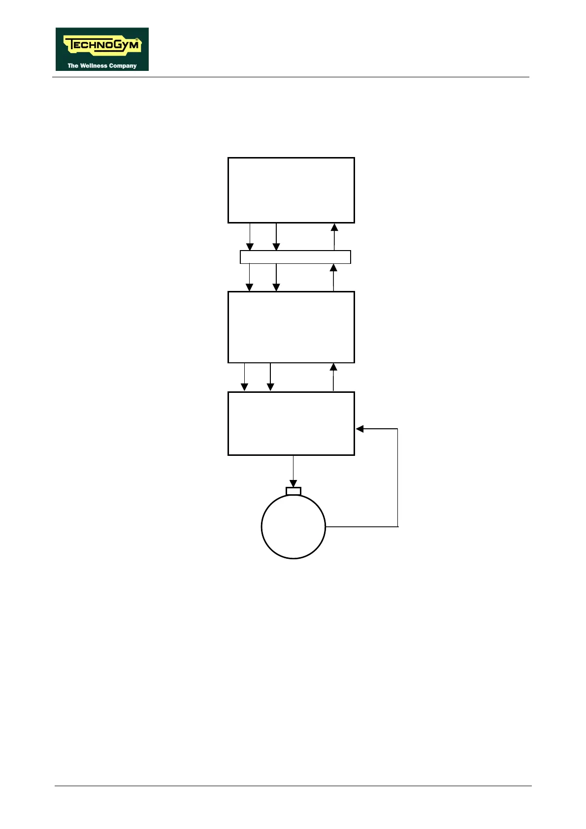
The machine controls the speed of the belt motor by means of the CPU board and the inverter
interface board, as shown in the following figure:
The speed control utilizes the following signals:
• Start signal
This is the signal generated by the CPU board to enable starting of the motor (pin 6-12 on
connector K4). When the tread-belt is stopped this signal is at logic level low (0.2 Vdc), whereas
immediately after the “Start” key on the display is pressed it goes high (4.8 Vdc).
This signal enters the driver board (pin 6-12 on connector J6), is processed and sent out (pin 2-1
on connector J5 of the driver board) to the inverter (pin 1-P24). In the belt-stopped conditions it
is -23.8 Vdc, while immediately after pressing the “Start” key on the display it is 0 Vdc.
Inverter
Alarm
Start Vref
O-L 1-P24 AL1-AL0
U-V-W
M
Thermal
protection
3-P24
VAC
with variable frequency
Driver board
4-12 6-12 8-12 J6
5-6 2-1 3-4 J5
Alarm
Start PWM
CPU board
4-12 6-12 8-12 K4
9-12 10-12 11-12 CN28
Alarm
Start PWM