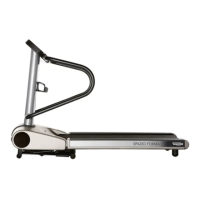
FORMA: Service & Maintenance manual - rev. 3.0
Page 3.9
3.3.3. T
HE SIGNALS INVOLVED
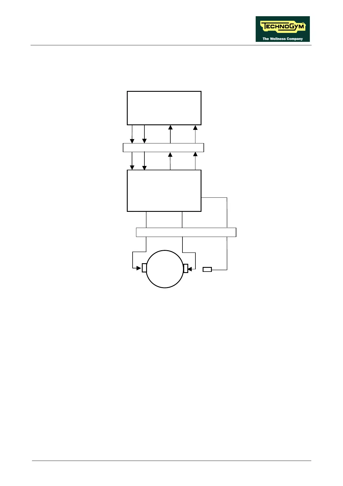
The machine controls the incline through the CPU board and the driver board, as illustrated in the
figure below:
The control logic involves the following signals:
• Up Signal
This is the signal generated by the CPU board (pin 5-12 on connector K4) to enable movement
of the up-down motor in the “up” direction. In normal conditions the signal is at logic level low
(0 Vdc), and it goes high (4.65 Vdc) to actuate the motor. The signal remains high for the entire
duration of the movement.
The signal enters the driver board (pin 5-12 of connector J6) and enables the movement of the
motor in the desired direction.
• Down signal
This is the signal generated by the CPU board (pin 3-12 on connector K4) to enable movement
of the up-down motor in the “down” direction. In normal conditions the signal is at logic level
low (0 Vdc), and it goes high (4.65 Vdc) to actuate the motor. This signal remains high for the
entire duration of the movement.
The signal enters the driver board (pin 3-12 on connector J6) and enables movement of the
motor in the desired direction.
3-12/CN25
Vdc
4-5/CN25
Reed sensor
M
Pulses
Alarm
CPU board
-
Driver
board
Pulses Down Up
-
9-11
-
-
9-11
K4
J6
-
-
7-12
-
2-12 1-12 4-5 CN28 3-12
Alarm Pulses Down Up