FORMA: Service & Maintenance manual - rev. 3.0
Page 3.12
3.4.3. T
HE SIGNAL INVOLVED
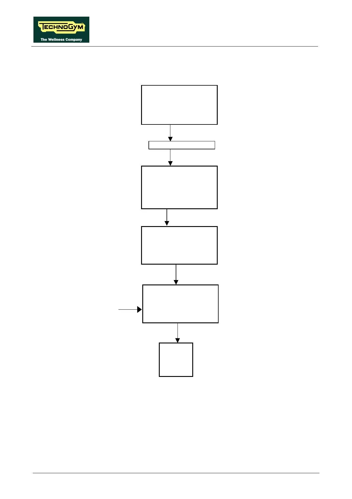
The machine controls the operation of the fan as illustrated in the diagram below:
• Start Signal
This is the signal generated by the CPU board to enable starting of the motor (pins 6-12 of
connector K4). When the treadmill is halted it is at logic level low (0.2 Vdc), and immediately
switches to logic level high (4.8 Vdc) when the "Start" button on the control panel is pressed.
This signal enters the driver board (pins 6-12 of connector J6), where it is processed and sent
(pins 2-1 of connector J5 on the driver board) to the inverter (pin 1-P24). When the treadmill is
halted it is at logic level low (-23.8 Vdc), and immediately switches to 0 Vdc when the "Start"
button on the control panel is pressed.
CN28
Inverter
Start
1-P24
Driver board
6-12
2-1 J5
Start
CPU board
6-12
10-12
Start
K4
J6
Fan interface board
2-1
CM2-L
IN
OUT
Fan
Enable