FORMA: Service & Maintenance manual - rev. 3.0
Page 6.26
Is the inverter control PWM
signal at the output of the
CPU board correct?
A
YES
Check and/or replace
cables RN-1 and/or RN-2
Replace the CPU board
NO
6
Follow the procedure step by step to correctly diagnose the problem. Take particular care with the
checks highlighted by circled numbers, which are described in detail below:
(1) See paragraph 9.5. to set the inverter and 8.6. to regulate the speed.
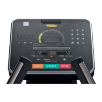
(2) When the machine is in operation, check that the speed shown on the display and the inverter
operating frequency are approximately those shown in the tables below, depending on whether
the machine is a Forma 2 or a Forma 3.
• Forma 2:
SPEED
(Km/h)
PWM SIGNAL
(Vdc)
ANALOG SIGNAL
(Vdc)
FREQUENCY
(Hz)
CPU BOARD DRIVER BOARD INVERTER
DISPLAY 4-12/K4 4-12/J6 5-6/J5 O-L DISPLAY
1.0 4.65 4.65 0.52 0.52 5.4
4.0 3.80 3.80 2.29 2.29 23.7
8.0 2.67 2.67 4.67 4.67 48.0
12.0 1.54 1.54 7.05 7.05 72.4
16.0 0.42 0.42 9.42 9.42 97
Table 6.6-1
• Forma 3:
SPEED
(Km/h)
PWM SIGNAL
(Vdc)
ANALOG SIGNAL
(Vdc)
FREQUENCY
(Hz)
CPU BOARD DRIVER BOARD INVERTER
DISPLAY 4-12/K4 4-12/J6 5-6/J5 O-L DISPLAY
1.0 4.73 4.73 0.52 0.52 4.2
4.0 4.06 4.06 2.4 2.4 19.5
8.0 3.17 3.17 4.89 4.89 40
12.0 2.27 2.27 7.4 7.4 60.2
16.0 1.38 1.38 9.9 9.9 80
Table 6.6-2