FORMA: Service & Maintenance manual - rev. 3.0
Page 6.30
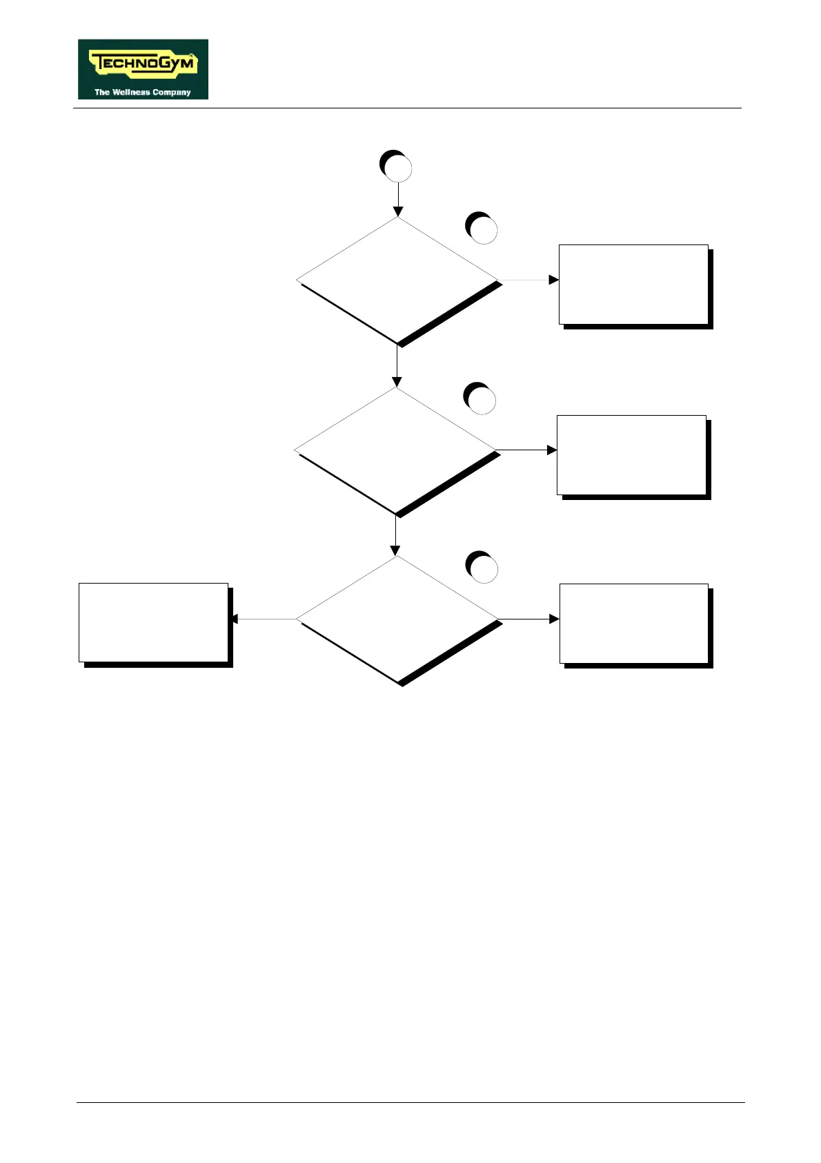
Does the encoder signal reach
the output of the driver board?
9
Replace the driver board
NO
YES
C
Does the encoder signal reach
trailing connector CN28
NO
Replace cable FR-12
YES
Does the encoder signal reach
the input of the CPU board?
NO
Replace cable FR-11
YES
Replace the CPU board
10
11
Follow the procedure step by step to correctly diagnose the problem. Take particular care with the
checks highlighted by circled numbers, which are described in detail below:
(1) Place the tester probes between pins 5 (signal) and 12 (ground) of connector K4 on the CPU
board. Press the “↑” key: the measured voltage should be approximately 4.65 Vdc. Place the
tester probes between pins 3 (signal) and 12 (ground) of connector K4 on the CPU board.
Press the “↓” key: the measured voltage should be approximately 4.65 Vdc.
(2) Place the tester probes between pins 2 (signal) and 12 (ground) of portable connector CN28.
Press the “↑” key: the measured voltage should be approximately 4.65 Vdc. Place the tester
probes between pins 1 (signal) and 12 (ground) of portable connector CN28. Press the “↓”
key: the measured voltage should be approximately 4.65 Vdc.
(3) Place the tester probes between pins 5 (signal) and 12 (ground) of connector J6 on the driver
board. Press the “↑” key: the measured voltage should be approximately 4.65 Vdc. Place the
tester probes between pins 3 (signal) and 12 (ground) on connector J6 of the driver board.
Press the “↓” key: the measured voltage should be approximately 4.65 Vdc.