FORMA: Service & Maintenance manual - rev. 3.0
Page 6.35
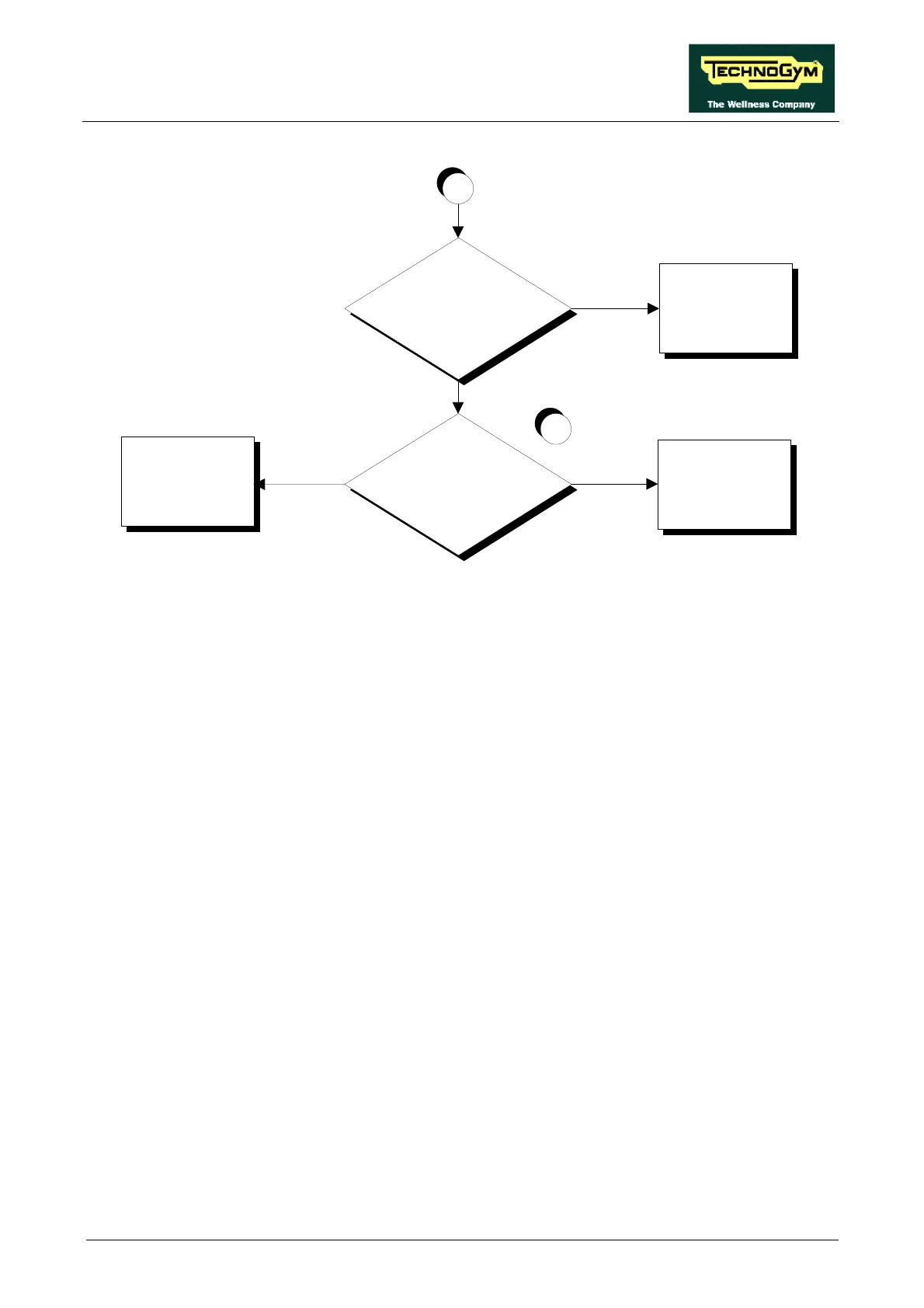
Does the motor draw the correct
current?
YES
NO
Replace the up-down
motor
Adjust the current limiter
on the driver board and/or
replace the driver board
Is there something obstructing
the movement of the machine?
NO
YES
A
3
Remove the obstruction
Follow the procedure step by step to correctly diagnose the problem. Take particular care with the
checks highlighted by circled numbers, which are described in detail below:
(1) To measure the encoder signal input to the driver board, place the tester probes between pins 5
(signal) and 6 (ground) of connector J1. To measure the encoder signal output by the driver
board, place the tester probes between pins 9 (signal) and 11 (ground) of connector J6.
(2) To measure the encoder signal output by the driver board, place the tester probes between pins
9 (signal) and 11 (ground) of connector J6. To measure the encoder signal input to the CPU
board, place the tester probes between pins 9 (signal) and 11 (ground) of connector K4.
(3) Place the tester probes in series with the motor cable. Press the “↑” or “↓” key: the steady-
state measured value should be less than 4÷5 A.