FORMA: Service & Maintenance manual - rev. 3.0
Page 6.37
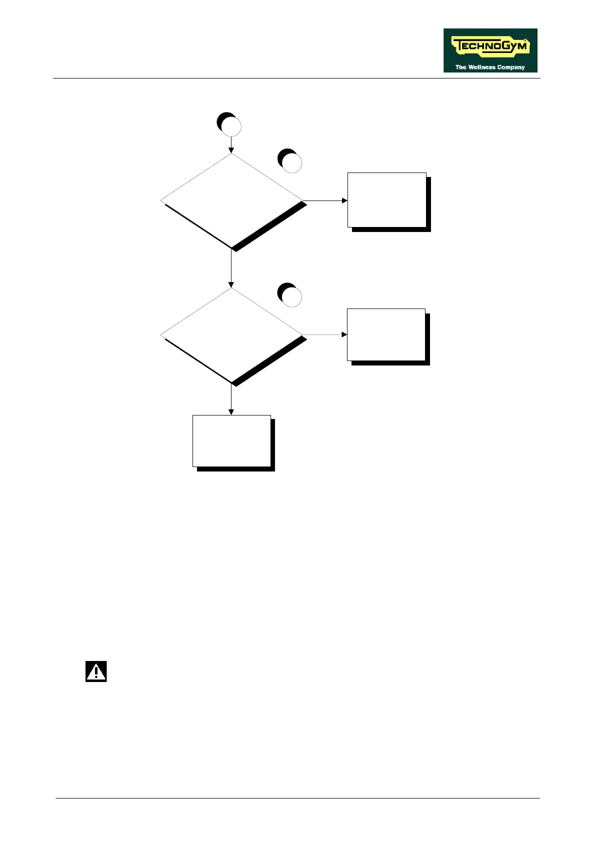
NO
Is the supply voltage correct at
the input to the f an?
6
Check/replace cable FR
-16
A
SI
Replace the f an
Is the supply voltage correct at
the output of the f an interf ace
board?
NO
SI
Replace the f an
interf ace board
5
Segui la guida passo a passo per una corretta diagnosi del guasto. In particolare presta attenzione
all’esecuzione dei controlli evidenziati dalle caselle numerate e qui di seguito dettagliati:
(1) Place the tester probes across the IN pins of connector CN2, check that the supply voltage is
correct: the measured value should be 220 VAC.
(2) Place the tester probes across pins CM2 and L of the inverter terminal block and check the
value of the enable fan signal: the measured voltage should be 24.55 Vdc.
(3) Check that the inverter parameters are correctly configured according to the procedure 9.5.
“Programming the HITACHI SJ100 inverter”.
WARNING: incorrect programming of the inverter can cause serious damage to
the machine or malfunctioning that is potentially hazardous to the user. Therefore,
attempt this operation only if certain of being able to carry out the procedure with
the latest SW version.
(4) Place the tester probes across pins 1 and 2 of connector CN1 on the component interface
board and check the value of the enable fan signal: the measured voltage should be 24.55 Vdc.