10.4 PGM TEST
To test PGM, proceed following process.
• LED Keypad;
[Fx] [8] → [Code XXXX] → [4] [1] → [√ OK] (PGM Test)
• LCD Keypad;
[Fx] [8] → [Code XXXX] → [4- PGM Test]→[√ OK]→[1] (PGM Test)
To exit test menu press [X] key.
10.5 PGM CONTROL
For PGM Control proceed following precess.
• LED Keypad;
[Fx] [8] → [Code XXXX] → [5] [1] → [√ OK] (PGM Control)
• LCD Keypad;
[Fx] [8] → [Code XXXX] → [5- PGM Control]→[√ OK]→[1] (PGM Control)
To exit test menu press [X] key.
11. APPLICATION
Basic information about operating the system according to various scenarios and applications and
how to program them according to these scenarios will be explained under this title.
11.1 FIRE DETECTOR CONNECTION WITH PGM OUTPUT
It is possible to take precautions against fire risks by connecting smoke detector to alarm panel. Fire
detectors trigger the alarm system when they detect smoke or heat in the environment and turn on
the red LED warning lights to give a visual warning on the detector.
When the detector detects it needs to be reset and returned to normal. This is achieved by cut the
power of the detector and received back. To prevent this from being physically accessed and
removed from the base, the detector supply can be supplied via the PGM output. In this way, when a
fire alarm occurs in the system and user code is entered to cancel alarm, the detector's supply can
be interrupted for a certain time and the detector can be reset. For this type of operation, both the
connection method and programming should be done as follows:
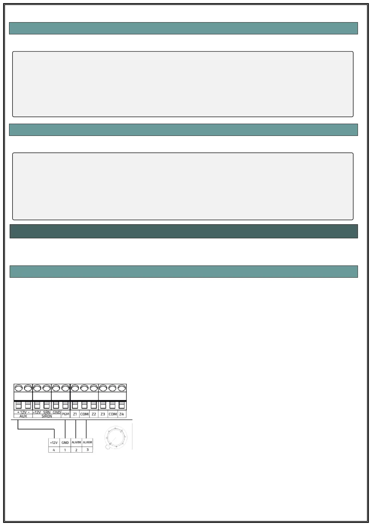
When the + 12V input of the smoke detector is connected to the
AUX output, the -12V input must be connected to the PGM
output. When the PGM output is programmed as “Fire
Detector”, the PGM output gives -12V. The time of the PGM
output will interrupt the feed is set in the PGM Parameter
section.