Maintenance
7–4
1502C MTDR Service Manual
5. Remove the power supply module from the instrument by moving it toward the
front of the instrument, guiding the power switch away from the mechanical
linkage assembly.
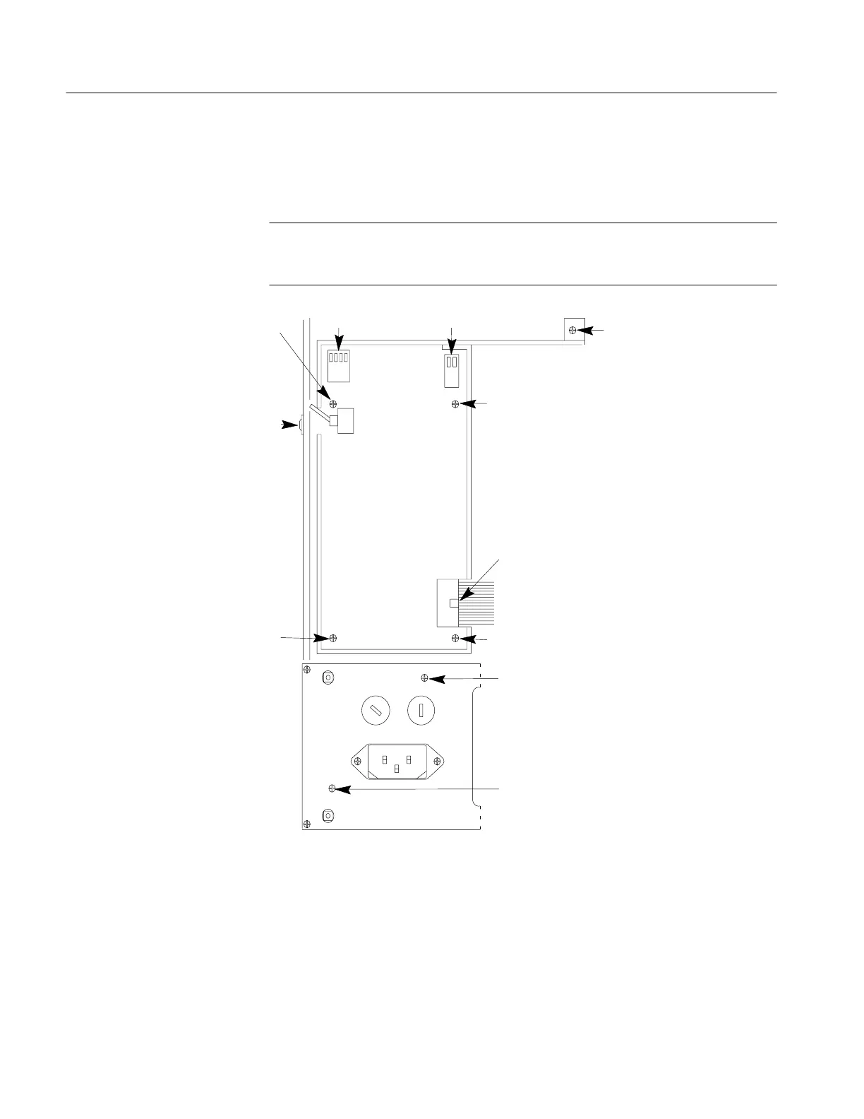
NOTE. The screws identified as 1 hold the circuit board to the module. They should
not be removed until you are ready to remove this circuit board from the module (next
procedure).
1
1
1
1
2
3
4
6
5
6
7
Top View
of
Power Supply
Module
End View
of
Rear Panel
Figure 7–2: Power Supply Module and P/O Rear Panel
1. Remove the power supply module per previous procedure.
2. Remove the two-conductor harmonica connector (Figure 7–2, 3).
3. Remove the four-conductor harmonica connector (Figure 7–2, 2).
Removing the Power
Supply Board
Artisan Technology Group - Quality Instrumentation ... Guaranteed | (888) 88-SOURCE | www.artisantg.com