Maintenance—2230 Service
9. With one hand firmly holding the Input/Output and
Vector Generator circuit board assembly and with the
other hand use a long-nose pliers on the top side to
squeeze and push the four circuit board spacers through
the holes in the Storage circuit board (see Figure 6-7 for
location of the circuit board spacers). Place the
Input/Output and Vector Generator circuit board assembly
inside the instrument temporarily to be reinstalled later.
10. Release the Board Latch and lower the Storage
circuit board into the instrument.
11. Disconnect the ribbon connector (P6100) from the
Input/Output and Vector Generator circuit board assembly.
12. Remove the Storage circuit board EMI clip from
the side chassis rail located behind the front hinge.
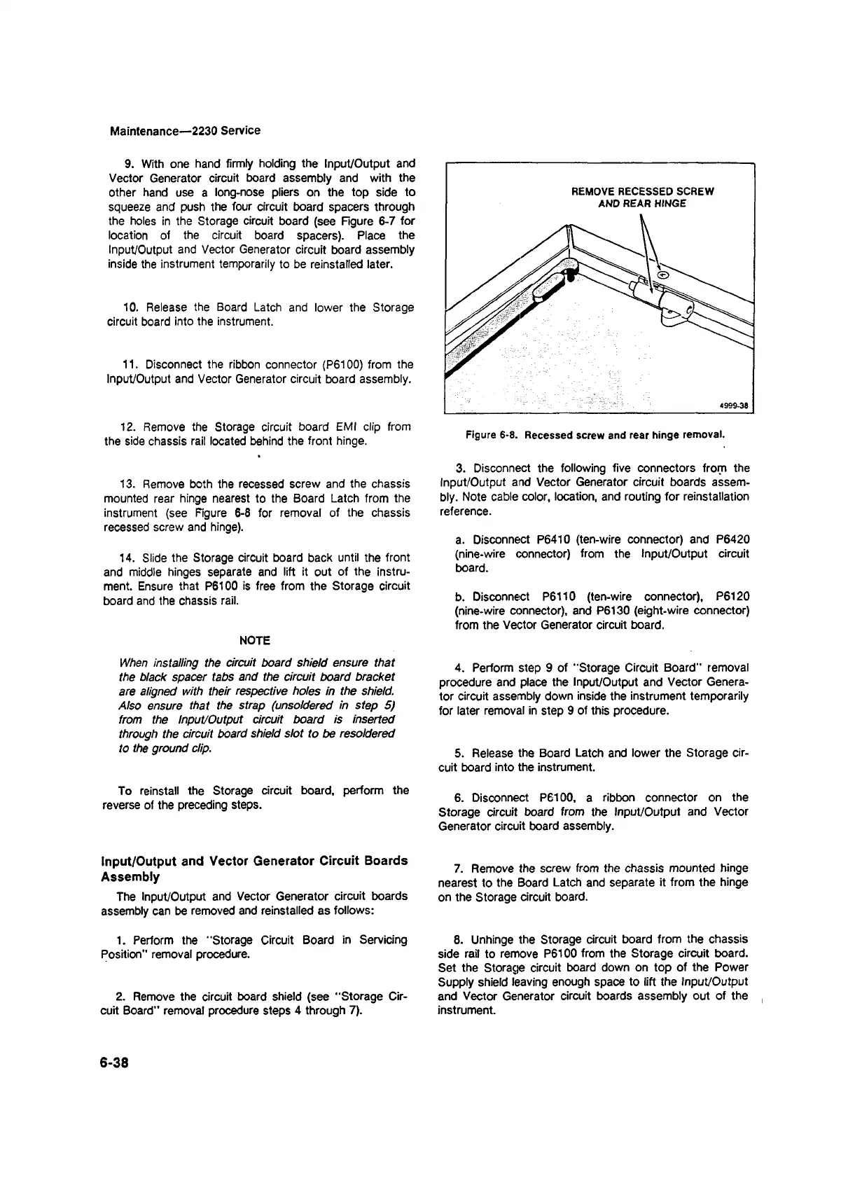
13. Remove both the recessed screw and the chassis
mounted rear hinge nearest to the Board Latch from the
instrument (see Figure 6-8 for removal of the chassis
recessed screw and hinge).
14. Slide the Storage circuit board back until the front
and middle hinges separate and lift it out of the instru
ment. Ensure that P6100 is free from the Storage circuit
board and the chassis rail.
NOTE
When installing the circuit board shield ensure that
the black spacer tabs and the circuit board bracket
are aligned with their respective holes in the shield.
Also ensure that the strap (unsoldered in step 5)
from the Input/Output circuit board is inserted
through the circuit board shield slot to be resoldered
to the ground clip.
To reinstall the Storage circuit board, perform the
reverse of the preceding steps.
Input/Output and Vector Generator Circuit Boards
Assembly
The Input/Output and Vector Generator circuit boards
assembly can be removed and reinstalled as follows:
1. Perform the "Storage Circuit Board in Servicing
Position" removal procedure.
2. Remove the circuit board shield (see "Storage Cir
cuit Board” removal procedure steps 4 through 7).
3. Disconnect the following five connectors from the
Input/Output and Vector Generator circuit boards assem
bly. Note cable color, location, and routing for reinstallation
reference.
a. Disconnect P6410 (ten-wire connector) and P6420
(nine-wire connector) from the Input/Output circuit
board.
b. Disconnect P6110 (ten-wire connector), P6120
(nine-wire connector), and P6130 (eight-wire connector)
from the Vector Generator circuit board.
4. Perform step 9 of “Storage Circuit Board" removal
procedure and place the Input/Output and Vector Genera
tor circuit assembly down inside the instrument temporarily
for later removal in step 9 of this procedure.
5. Release the Board Latch and lower the Storage cir
cuit board into the instrument.
6. Disconnect P6100, a ribbon connector on the
Storage circuit board from the Input/Output and Vector
Generator circuit board assembly.
7. Remove the screw from the chassis mounted hinge
nearest to the Board Latch and separate it from the hinge
on the Storage circuit board.
8. Unhinge the Storage circuit board from the chassis
side rail to remove P6100 from the Storage circuit board.
Set the Storage circuit board down on top of the Power
Supply shield leaving enough space to lift the Input/Output
and Vector Generator circuit boards assembly out of the
instrument.
6-38