Options—2230 Service
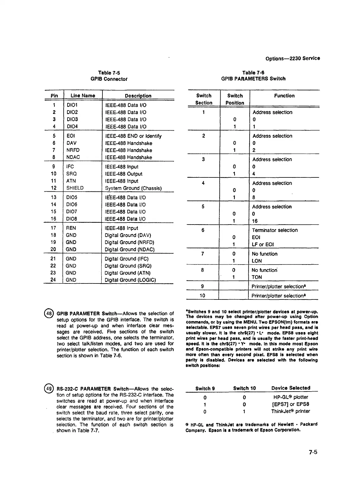
Table 7-5
GPIB Connector
Pin Line Name
Description
1
DIOI
IEEE-488 Data I/O
2
DI02
IEEE-488 Data I/O
3 DI03
IEEE-488 Data I/O
4 DI04
IEEE-488 Data I/O
5 EOI
IEEE-488 END or Identify
6 DAV
IEEE-488 Handshake
7
NRFD
IEEE-488 Handshake
8
NDAC
IEEE-488 Handshake
9 IFC
IEEE-488 Input
10 SRQ
IEEE-488 Output
11 ATN
IEEE-488 Input
12
SHIELD
System Ground (Chassis)
13
DI05
IEfcE-488 Data I/O
14
DI06
IEEE-488 Data I/O
15
DI07
IEEE-488 Data I/O
16
DI08
IEEE-488 Data I/O
17 REN
IEEE-488 Input
18
GND
Digital Ground (DAV)
19
GND
Digital Ground (NRFD)
20 GND
Digital Ground (NDAC)
21
GND
Digital Ground (IFC)
22
GND
Digital Ground (SRQ)
23 GND
Digital Ground (ATN)
24
GND
Digital Ground (LOGIC)
^ 8 ) GPIB PARAMETER Switch—Allows the selection of
setup options for the GPIB interface. The switch is
read at power-up and when interface clear mes
sages are received. Five sections of the switch
select the GPIB address, one selects the terminator,
two select talk/listen modes, and two are used for
printer/plotter selection. The function of each switch
section is shown in Table 7-6.
(49 ) RS-232-C PARAMETER Switch—Allows the selec
tion of setup options for the RS-232-C interface. The
switches are read at power-up and when interface
clear messages are received. Four sections of the
switch select the baud rate, three select parity, one
selects the terminator, and two are for printer/plotter
selection. The function of each switch section is
shown in Table 7-7.
Table 7-6
GPIB PARAMETERS Switch
Switch
Section
Switch
Position
Function
1 Address selection
0 0
1
1
2 Address selection
0
0
1
2
3 Address selection
0
0
1 4
4
Address selection
0 0
1 8
5 Address selection
0 0
1
16
6 Terminator selection
0 EOI
1
LF or EOI
7
0
No function
1
LON
8
0 No function
1
TON
9
Printer/plotter selection®
10 Printer/plotter selection®
‘Switches 9 and 10 select printer/plotter devices at power-up.
The devices may be changed after power-up using Option
commands, or by using the MENU. Two EPSON(tm) formats are
selectable. EPS7 uses seven print wires per head pass, and is
usually slower. It is the chr$(27) • L* mode. EPS8 uses eight
print wires per head pass, and is usually the faster print-head
speed. It is the chr$(27)' Y* mode. In this mode most Epson
and Epson-compatible printers will not strike any print wire
more often than every second pixel. EPS8 is selected when
parity is disabled. Devices are selected with the following
switch positions:
Switch 9
Switch 10
Device Selected
0
0
HP-GL® plotter
1
0
[EPS7] or EPS8
0
1
ThinkJet® printer
8 HP-QL and ThlnkJet are trademarks of Hewlett ■ Packard
Company. Epson is a trademark of Epson Corporation.
7-5