Get Acquainted w
ith the Instrument
17. The g roup icon i
ndicates when digital
channels are grouped (MSO3000 Series
only).
18. The bus display shows decoded packet
level information for serial buses or for
parallel bus
es (MSO3000 Series only).
The bus indicator shows the bus number
and bus type.
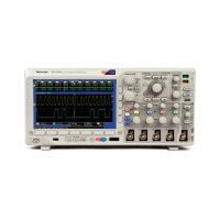
Front-Pan
el Connectors
1. Input R ang
e +30 V to –20 V connector
for the P6316 digital probe on
MSO3000 models only.
2. Channel 1, 2,(3, 4). Channel inputs with
the TekVP
I Versatile Probe Interface.
3. Aux In.Tr
igger level range is adjustable
from +8 V to –8 V. The maximum input
voltage is 450V peak, 300V RMS. Input
resista
nce is 1 M Ω ± 1% in parallel w ith
11.5 pF ±2 pF .
4. PROBE COMP. Square wave signal
source to compensate probes. Output
voltag
e: 0 – 2.5V, amplitude ± 1% behind
1kΩ ±2%. Frequency: approximately
1kHz.
5. Ground.
6. Application Module Slots.
MSO3000 and DPO 3000 Series Oscilloscopes User Manual 41
 Loading...

