HD3G7 HD 3 Gb/s SDI Video Generator module
HD3G7 m odule
TRIGGER O UTP UT
submenu
Usethismenuto
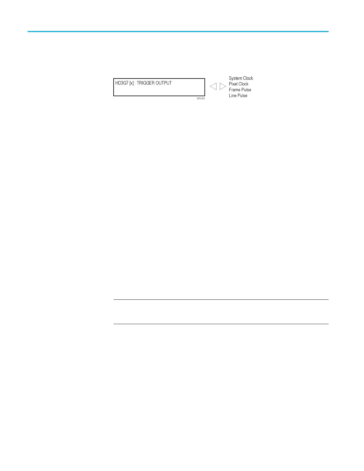
select line rate, frame rate, or the syste m clock of the module
to trigger an external instrument. The following figure shows the TRIGGER
OUTPUT submenu.
Figure 3-96: HD3G7 module TRIGGER OUTPUT submenu
System Clock. The system clock is a low-jitter c lock signal, which runs at the
parallel c
lock rate for 3G formats or twice the parallel clock rate for HD formats.
Pixel Clock. The pixel clock is an internal parallel rate clock (a low frequency
clock related to the pixel rate of the video signal).
Frame / Field Pulse. The trigger pulse is produced at the field or frame rate of
the vide
o signal. In interlaced and segmented-frame formats, this produces a
frame-rate square wave that is low during field one and high during field two.
In progressive formats the output is high during the vertical blanking period,
producing a field-rate pulse.
1
Line Pulse. The trigger pulse output is high during the horizontal blanking period,
prod
ucing a line-rate pulse.
1
1
The Frame/Field Pulse and Line Pulse signals are derived from the EAV and SAV XYZ byte H, V, and F bits,
just
prior to the parallel data entering the serializer; therefore these pulses can be used to approximate the
signal timing.
HD3G7 m odule
SECO
NDARY OUTPUT
submenu
Use the left (◄)orright(►) arrow button to select be tween a Test Signal or a
Bla
ck output for the secondary (Signal 2) BNC c onnector, and then press the
ENTER button to confirm the selection.
NOTE. When set for a Test Signal, the Signal 2 output is the same as the Signal 1
output. When set to Black, the black signal is the same format and sample
structure as the Signal 1 output.
3–208 TG8000 Multiformat Test Signal Generator User Manual

 Loading...


