Getting started
3. Check that no er
ror messages appear on the display.
4. Warm up the instrument for 20 minutes.
SIGNAL output.
5. Use the 75 Ω BNC cable to connect the SIGNAL connector to one of the
input connectors on the waveform monitor rear panel.
6. Use the 75 Ω terminator to terminate the other loop through connector on the
waveformmonitorrearpanel.
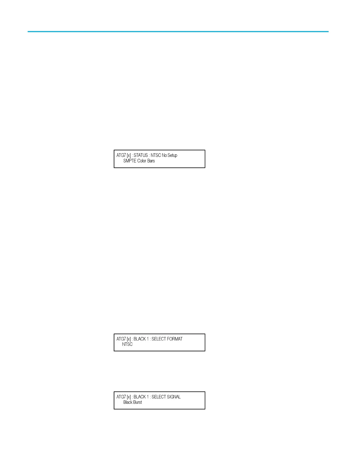
7. Press the front-panel MODULE button until the ATG7 main menu shown
below appears .
8. Press the front-panel FORMAT button and use the left (◄)orright(►)
arrow button to select NTSC or PAL.
9. Press one of the front-panel test signal buttons (for example COLOR BAR)
to output a signal
.
10. Set the waveform monitor to view the signal.
11. Check that the signa l appears as expected. For example, if you selected a
color bars signal in step 7, check that the color bars signal appears.
BLACK 1 and BLACK 2 outputs.
12. Disconnect the BNC cable from the SIGNAL connector, and then connect it
to the BLACK 1 connector.
13. Press the up (▲)ordown(▼)arrowbuttontoselectSELECT OUTPUT
from the main menu.
14. Press the left (◄)orright(►)arrowbuttontoselectBLACK 1.
15. Press the front-panel ENTER button. The SELECT FORMAT submenu
shown below appe ars.
16. Press the left (◄)orright(►) arrow button to select NTSC or PAL.
17. Press the ENTER button. The SELECT SIGN
AL submenu s hown below
appears.
1–20 TG8000 Multiformat Test Signal Generator User Manual

 Loading...


