72
GPON ONT
Parameter Description
Local IP
Public IP address of the routing device where the tunnel is being congured, (Refs.
769501-769502 of network A in the shown example), Figure 5-53.
Remote IP
Public IP address of the routing device terminating the GRE Tunnel in the other ex-
treme of the tunnel (Refs. 769501-769502 of network B in the shown example), Fig-
ure 5-53.
Tunnel Name GRE Tunnel Identication (string)
GRE Tunnel IP
IP address of GRE Tunnel interface, on the routing device being congured (Refs.
769501-769502 of network A in the shown example), Figure 5-53.
GRE Tunnel Mask
IP address of GRE Tunnel interface, on the routing device terminating the GRE Tunnel
in the other extreme of the tunnel (
Refs. 769501-769502 of network B in the shown
example), Figure 5-53.
TTL Time to Live value
Table 5-14:GRE Tunneling Settings – Advanced conguration mode parameters
After entering the required information, use Next button to progress to the next window, WAN Service setup window- GRE Tunneling Settings –
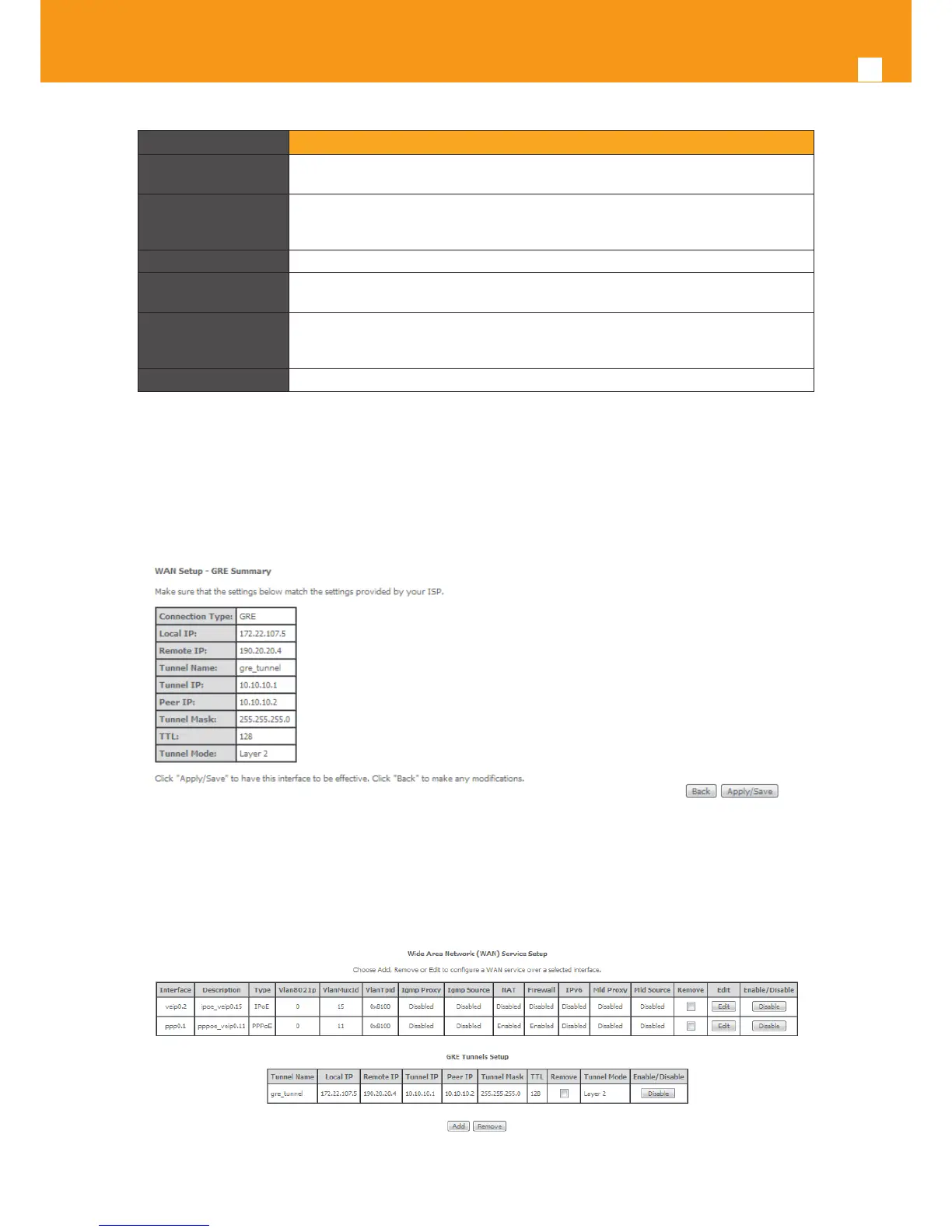
GRE Summary, Figure 5-61. This table should reect the conguration for the GRE-Tunnel service setup parameters than have been congured.
Please verify the presented conguration match the settings provided by the ISP for this service.
Figure 5-61: WAN Service setup window- GRE Tunneling Settings – GRE Summary
To nalize the conguration use the Save/Apply button, Figure 5-61. The next displayed window is initial window, the WAN Service Window, where
the service congured is displayed in the corresponding table, Figure 5-62.
Figure 5-62: WAN Service Setup Initial Window- service conguration displayed
 Loading...