TCS5500
Page | 11
TMS room equipment
From the central unit a TMS-network starts consisting of interface
units. On these interface units, microphones, channel selectors,
voting panels and loudspeaker units are connected. There are
models to be placed on the table and others are surface mounted.
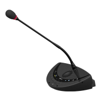
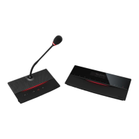
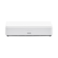
Delegate controller interface (INT5500)
4 microphones and 4 channel selectors, voting or loudspeaker units
can be connected to the interface using the MIC RJ-48 and DCS
RJ-45 connector sockets. These different units can be combined to
satisfy the user demands. Some possible connection configurations
are graphically summarized in appendix A.
The interface unit has two RJ-45 shielded connector sockets
labeled IN and OUT, which will be used to connect the interface to:
1. the central unit
Use a system cable that interconnects the TMS1 (2, 3 or 4)
RJ-45 shielded connector socket from the CPU5500 and
the RJ-45 socket labeled IN.
2. another interface unit
Interconnect IN (interface) to OUT (previous interface
unit) with a system cable.
3. an extension unit
Connect the interface to a port on the extension unit. An
EU5500 can extend the network with 8 branches.