EasyManua.ls Logo

Televic TCS5500 - Central Unit (CPU5500); CPU5500 Basic Equipment

Televic TCS5500
125 pages
Print Icon
To Next Page IconTo Next Page
To Previous Page IconTo Previous Page
Loading...
TCS5500
Page | 25
Central unit
Basic equipment of the central unit (CPU5500)
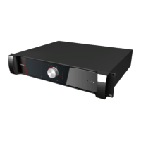
The heart of the TCS5500 system is the central unit CPU5500. At
the back of the central unit you can see the in- and outputs of the
different boards present in the central unit. The numbers on the
figure correspond with the explanation below in the figure.
4
TELNET
MONITORING
F1 F2
STATUS
FTP
FLOOR
PC TMS
PC TIS
F3
ENTER
EXIT
CAMERA
OP. DESK
5 6 7 8 9321 10
Fig.: CPU5500 front
WARNING
PERSONNEL ONLY.
T 3.15 A L ( 230 V)
T 7 A L ( 115 V)
HAZARD.
AUTHORIZED
ELECTRICAL
LANCOM 1KEYB VGA
AUX OUT 6
AUX OUT 5 :
CONTROL IN 1 :
CONTROL OUT :
AUX OUT / CONTROL
AUX OUT 3 :
AUX OUT 4 :
11
12
3
4
AUX OUT 1 :
AUX OUT 2 : 10
9
2
1
( )
( )
8 MAX+5V
7
(c)
15
5
6
/ : 14
13
AUX OUT 1
USB - FDD
COM 2
LPT1
AUX OUT /
CONTROL
AUX IN 2
2
AUX IN 1
3
1
115 - 230 V
PORT 5
TMS
PORT 1 PORT 2 PORT 4
COUPLING
PORT 3
CLK INFOTIS
PORT 8PORT 6
COUPLING
COUPLING
PORT 7 PORT 10PORT 9
7 - 3.5 A
50 / 60 Hz
14 15 16 17 18131211 19 20 21 22 23
25 2624 27 28 29 30
Fig.: CE5500 rear
1. Headphone connection, 3.5 mm jack socket.
2. Monitor loudspeaker
3. LED status indicators for following items:
STATUS: flashes during boot-up, on when CPU up
and running
FLOOR: at least one microphone activated
PC TMS: PC control suite CONFSYS (microphone
management) running and connected to the
CPU5500

Table of Contents

Related product manuals