Page | 24
TIS Interpreter equipment
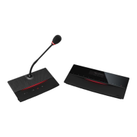
Interpreter desk (ID5500)
The interpreter desk has 2 RJ-45 jacks to interconnect the desk in
the TIS network. The RJ jacks are labeled IN and OUT. Via a
system cable the interpreter desk can be connected to the central
unit or on the previous interpreter desk.
The TIS network can be configured as a branched network. The
picture below shows the configuration.
relay 1 relay 2 relay 3 relay 4 relay 5
A B
relay
ls n.
TCS 5500-D
relay 1 relay 2 relay 3 relay 4 relay 5
A B
relay
ls n.
TCS 5500-D
relay 1 relay 2 relay 3 relay 4 relay 5
A B
relay
ls n.
TCS 5500-D
relay 1 relay 2 relay 3 relay 4 relay 5
A B
relay
ls n.
TCS 5500-D
Fig.: Branched network
The RJ-45 IN connector on the interpreter desk has to be connected
to a TIS RJ-45 connector on the central unit or to a RJ-45 OUT
connector on the previous ID5500.
At the bottom of the interpreter desk there is also a RJ-45 OUT
connector that can be connected to another interpreter desk.
The goose-neck microphone (TGM404, TGM407) is connected via a
5pins XLR connector.
A headset can be connected via the 7pins circular DIN connector.
The ID5500 is also provided with two 3.5mm jack sockets for an
external microphone and headphone.
The EXT and INT led input or an ON-AIR lamp use a RJ45 8-pin
connector.
By pushing the slow down button on the ID5500 you can alert the
chairman that speakers are talking too fast. For other functionalities
please refer to the ID5500 documentation.
For more information, please refer to the manual:
TIS5500 Conference & Interpretation System, Software User’s
Guide to TIS5500.